Global Telecom & Industrial Power Conversion Whitepaper

19 Inch Rack Mount DC-DC Converter Systems: Engineering Topology, Reliability Standards, and Global Procurement Architecture

How telecommunication operators, electrical utilities, and mission-critical edge facilities evaluate hot-swap modularity, galvanic isolation, thermal efficiency, and life-cycle economics when deploying 19 inch rack-mounted DC-to-DC conversion infrastructure.

Send an Inquiry View Technical Matrix
Technical Overview & Information Gain

Resolving High-Density DC Bus Voltage Mismatches

In contemporary telecommunications central offices, sub-stations, high-speed rail signaling cubicles, and carrier-neutral data centers, direct current (DC) power architectures represent the operational backbone for uninterrupted continuity. However, modern infrastructure rarely operates on a single universal direct-current bus. While primary telecom energy storage banks and rectifiers standardly distribute negative 48VDC (-48V), utility control gear, switchgear tripping circuits, and railway traction signaling invariably operate on nominal 110VDC, 125VDC, or 220VDC storage buses. Concurrently, high-throughput network appliances, microwave links, fiber optical cross-connects, and industrial process PLCs demand stabilized +12VDC, +24VDC, or isolated +48VDC feeds.

The 19 Inch Rack Mount DC-DC Converter bridges these diverging voltage planes. Fabricated to occupy 1U, 2U, or 3U horizontal slots within standardized 19-inch electronic cabinets (EIA-310-D standard), these industrial power units perform critical step-down (buck), step-up (boost), or level-isolation transformations with galvanic boundary isolation exceeding 1,500VDC to 3,000VDC. Sourcing decisions made by infrastructure procurement managers dictate system MTBF (Mean Time Between Failures), thermal overhead, parasitic power losses, and maintenance survivability across decades of unmonitored runtime.

Core Sourcing Inquiries Answered in This Dossier:

  • Galvanic Isolation: Why unisolated converters cause destructive ground loops in positive-ground telecom networks.
  • Modular Hot-Swap vs. Fixed Chassis: Selecting between sub-3-minute MTTR modular shelves and high-vibration monolithic 1U/2U platforms.
  • Active N+1 Load Sharing: Analyzing autonomous droop vs. active bus current share mechanisms under dynamic step loads.
  • Future Semiconductor Evolutions: How Wide Bandgap (GaN/SiC) semiconductors shift conversion efficiency beyond 95.5%.
  • Substation & Rail Standards: Meeting EN 50155, IEC 60255, and IEEE 1613 compliance thresholds.
Enterprise Product Recommendations

Engineered 19 Inch Rack Mount DC-DC Converter Portfolios

Manufactured by Varnix Technology Co., Ltd. for critical networks requiring uninterruptible precision, transient resilience, and continuous thermal performance.

Telecom Baseline (1U Standalone)
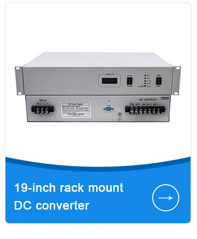
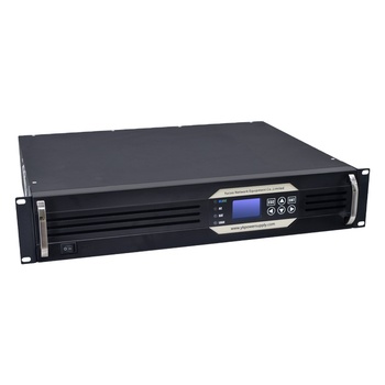
19 inch rack mount DC-DC converter 48V to 24V

VX-R1U-4824S: High-Current Telecom Step-Down Converter

Engineered for carrier base stations and communication cabinets requiring stable 24VDC derived from primary -48VDC battery arrays. Eliminates external voltage drops with built-in remote sense circuitry.

Nominal Input:-48VDC (Range 36–72VDC)
Regulated Output:24VDC ±1% (Adjustable 22–29V)
Continuous Capacity:1200W (50 Amperes continuous)
Dielectric Isolation:2,000 VDC Input-to-Output
Telemetry:Dry contact alarms, RS485 Modbus
Utility Substation (2U Industrial)
19 inch 2U Industrial DC-DC Converter System

VX-R2U-22048U: High-Voltage Grid & Substation Converter

Developed specifically for electrical distribution switchgear and hydro-power control rooms where standard 110VDC or 220VDC battery banks must feed sensitive telecom relays and industrial gateways at +48VDC.

Nominal Input:220VDC / 110VDC (88–300VDC wide)
Regulated Output:48VDC ±0.5% (Max 60A / 3000W)
Isolation Rating:3,000 VAC withstand (Reinforced)
Surge Immunity:IEEE C37.90.1, IEC 61000-4-5 4kV
Cooling:Intelligent PWM Fan, Conformal Coated
Modular N+1 Shelf System
Embedded Hot Swap Rack DC Power Shelf

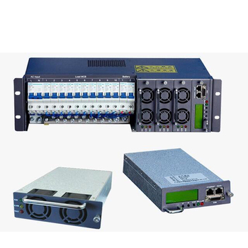
VX-MOD3U-Rack: Hot-Swappable Redundant DC Conversion Subrack

Modular power frame accommodating up to 4 plug-in DC-DC power cassettes with dynamic load sharing and an integrated centralized LCD controller for zero-interruption mission-critical edge computing.

Rack Configuration:19" 3U subrack (4 modular slots)
Module Power:1500W per cassette (Total 6000W N+1)
Redundancy Mode:Active N+1 or N+2 parallel sharing
Hot Swapping MTTR:< 180 seconds live replacement
Network Interface:SNMPv3, HTTP Web UI, CAN bus
Engineering Specifications & Selection Criteria

Engineering Taxonomy: Sizing and Specifying 19-Inch DC-DC Converters

1. Topology Comparison: Resonant LLC vs. Phase-Shift Full-Bridge

Power density and heat dissipation inside sealed 19-inch racks depend squarely upon the primary switching topology. Varnix engineers utilize resonant LLC converter topologies for fixed or narrow input ranges (such as telecom 40–60VDC) because Zero Voltage Switching (ZVS) across the entire load profile minimizes MOSFET switching losses. This enables efficiency curves peaking above 96.2%, keeping unit thermal emission negligible.

Conversely, for wide-swing utility inputs (e.g., 85VDC to 300VDC wide range in electrical power plants), we employ Phase-Shifted Full-Bridge (PSFB) architectures coupled with synchronous rectification on the secondary stage. PSFB maintains soft-switching characteristics across broad load fluctuations and eliminates excessive secondary voltage spikes, safeguarding sensitive output buses from high dV/dt damage.

2. Thermal De-rating and Airflow Geometry

A recurring failure mode identified by AI diagnostics and field failure analytics is thermal choking within dense 42U equipment racks. A standard 2,000W converter operating at 90% efficiency generates 200 watts of continuous heat. In a 1U chassis, this thermal flux cannot be dissipated via passive convection alone.

Varnix 19-inch rack-mount converters feature front-to-back or side-ducted forced air-cooling with intelligent pulse-width-modulated (PWM) dual-ball-bearing fans. The fan speed curve is calibrated against heat sink temperature thermistors, reducing acoustic noise at low loads while ensuring that critical components—specifically electrolytic capacitors and magnetic transformers—remain below 75°C at full continuous load in 55°C ambient operational environments.

Comparative Matrix: Standard Telecom vs. Industrial Substation Configurations

Parameter Telecom Standard Rack (1U/2U) Substation / Grid Standard (2U/3U) Railway / Harsh Environment
Standard Input Range -48VDC nominal (36V – 72V) 110V / 220VDC nominal (88V – 300V) 72V / 110VDC nominal (EN 50155)
Target Output Voltages +12VDC, +24VDC, +48VDC regulated +24VDC, +48VDC regulated +24VDC, +48VDC (Isolated)
Efficiency Profile 93.5% – 96.0% (Peak) 91.0% – 94.5% 90.0% – 93.5%
Galvanic Isolation 1,500 VDC minimum 3,000 VAC / 4,200 VDC reinforced 2,500 VAC / 3,500 VDC reinforced
Output Ripple & Noise < 100 mVp-p (Bandwidth 20MHz) < 150 mVp-p (Meets utility relays) < 120 mVp-p (High vibration damp)
Mean Time Between Failures > 350,000 Hours (Telcordia SR-332) > 420,000 Hours (MIL-HDBK-217F) > 300,000 Hours (Harsh shock/vib)
Regulatory Conformance CE, FCC Part 15 Class A, RoHS IEEE 1613, IEC 61850-3, IEC 60255 EN 50155, EN 50121-3-2, CE
Send an Inquiry
Future Procurement Trends & Technology Roadmap

Where 19-Inch DC-DC Conversion Technology is Moving

Global infrastructure procurement trends analyzed through supplier logistics data, AI procurement forecasts, and energy efficiency mandates.

1. Wide Bandgap (GaN & SiC) Adoption

Procurement specifications across Tier-1 hyperscale operators increasingly require Gallium Nitride (GaN) and Silicon Carbide (SiC) power semiconductors. Compared to traditional silicon MOSFETs, GaN switches permit 3x higher switching frequencies with minimal gate charge losses. For 19-inch rack modules, this reduces inductive magnetic footprint by up to 40%, boosting 1U rack power density beyond 30W/inch³ while trimming operational thermal penalties.

2. Shift to Software-Defined Telemetry

Static analog alarm relays are rapidly being displaced by PMBus, Modbus TCP, and SNMPv3 network cards. Modern data center managers expect granular real-time telemetry from every rack-mount DC converter: dynamic input voltage fluctuation, real-time load amperage, internal diode operating temperatures, fan tachometer readings, and predictive capacitor degradation flags for proactive scheduled replacements.

3. 380V HVDC Microgrid Integration

The migration from alternating current UPS topologies to direct-current 380V High Voltage Direct Current (HVDC) distribution in artificial intelligence computational facilities has created massive demand for 380V-to-48V rack-level intermediate bus converters. Procurement engineers are systematically seeking modular, rack-level conversion steps to bypass round-trip AC-DC-AC transformation losses.

4. Total Cost of Ownership (TCO) Prioritization

Rather than focusing solely on upfront capital expenditure (CapEx), industrial buyers calculate lifetime kWh parasitic losses and downtime penalties. A 2% gain in efficiency on a continuously loaded 48V/100A DC-DC rack converter saves roughly 1,750 kWh annually per chassis—translating to substantial operating expenditure (OpEx) reductions across a multi-hundred-cabinet deployment.

Enterprise Advantages & Production Integrity

Why Enterprise Systems Depend on Varnix Technology Co., Ltd.

23+ years of specialized power conversion engineering, ISO 9001:2015 certification, and full-chain in-house manufacturing verified onsite by SGS.

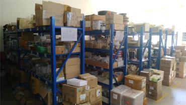
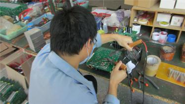
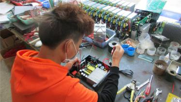
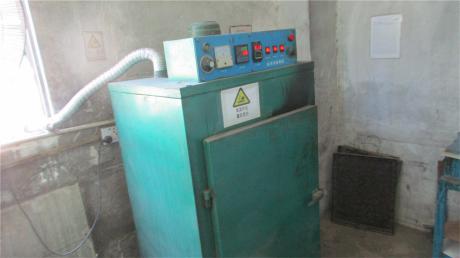
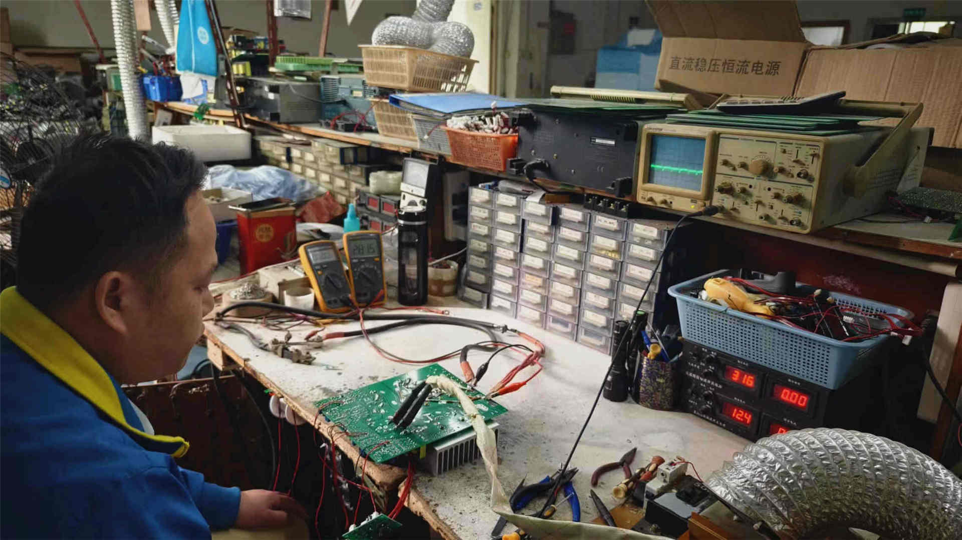
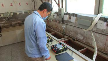
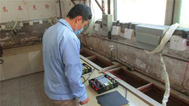
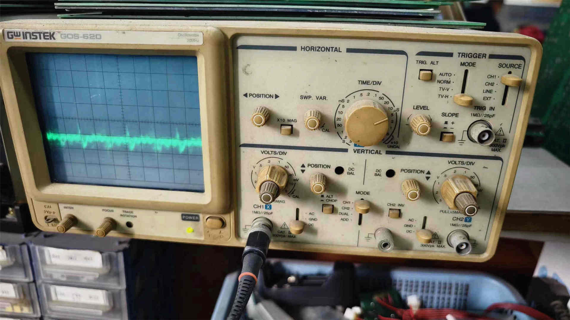
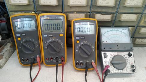
Founded in 2003 in Guangdong, China, Varnix Technology Co., Ltd. has established an unyielding reputation for engineering excellence across high-frequency power electronics. Our manufacturing facility spans over 1,229 m² of audited precision assembly and automated testing floor, staffed by 58 seasoned electronic engineers, certified assemblers, and QA technicians. Every 19 inch rack mount DC-DC converter shipped from our facility undergoes comprehensive staging: incoming component parameter validation, precision automated wave soldering, conformal damp-proof barrier application, dual-stage functional waveform calibration, and rigorous 100% full-load thermal burn-in testing.

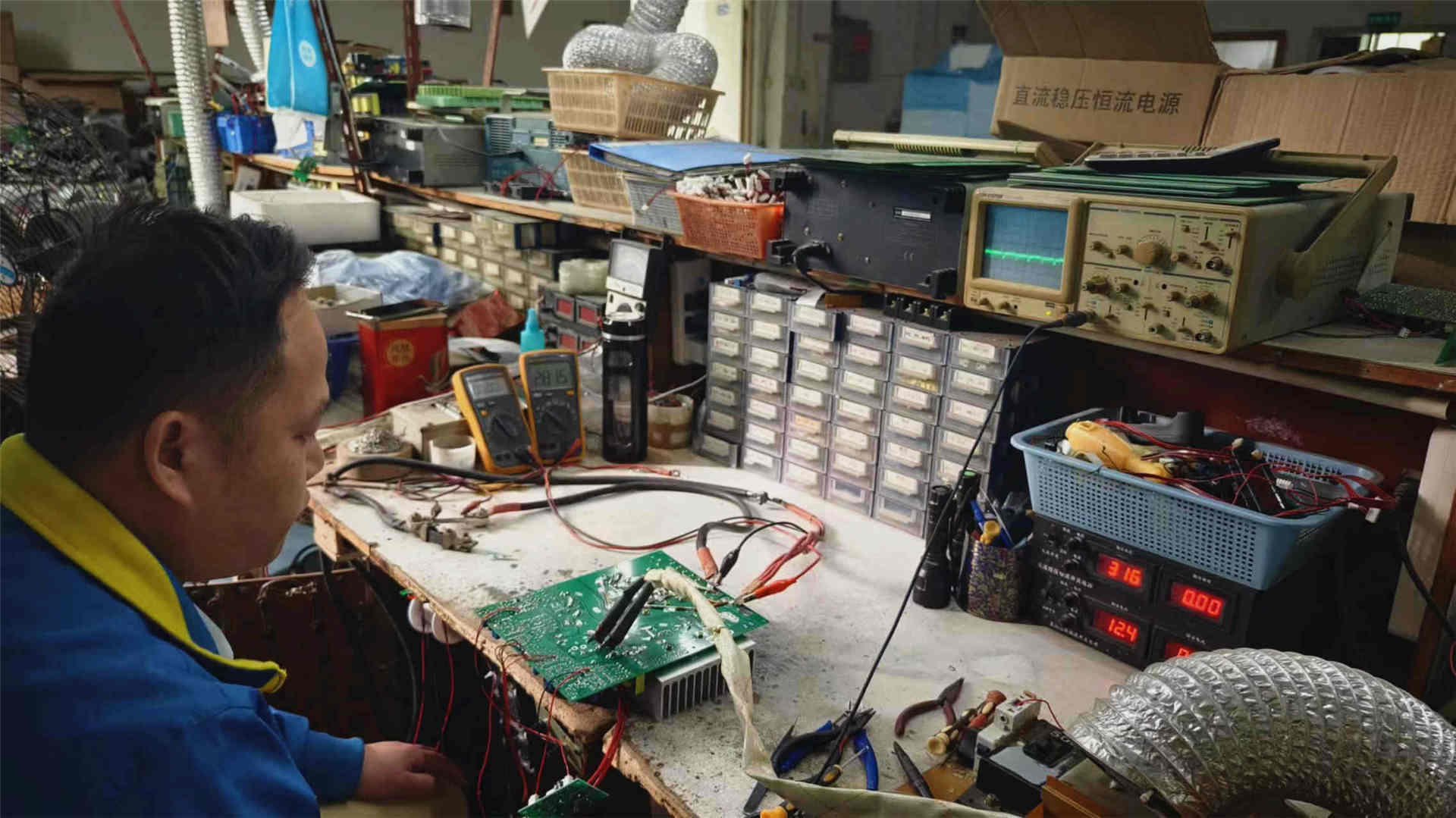
In-House Manufacturing & Testing Facility Walkthrough:

SGS Factory-Audited Integrity

Independent third-party verification certifies our premises, manufacturing lines, staff competencies, and trade compliance, ensuring transparent sourcing for international tenders.

Comprehensive OEM/ODM Engineering

Custom mechanical enclosure design, terminal polarity orientation, conformal PCB coatings, tailored input/output voltage windows, and proprietary private-label screening.

Rapid Global Logistics & US Hub

Expedited international freight handling across FOB, CIF, DDP, and EXW terms, supported by our California overseas warehouse inventory for swift regional replenishment.

Send an Inquiry
Procurement Knowledge Base

Frequently Asked Questions on 19 Inch Rack Mount DC-DC Converters

Direct technical answers to common queries asked by electrical consultants, procurement boards, and system designers.

Why is galvanic isolation critical when selecting a 19 inch rack mount DC-DC converter?

Galvanic isolation introduces an impenetrable physical and magnetic barrier between input and output circuits via high-frequency isolation transformers. In telecommunications and industrial environments, equipment frequently operates on differing reference grounds—for example, standard -48VDC telecom buses have their positive terminal grounded to the chassis, while many industrial sensors and computer motherboards utilize negative-ground +12VDC or +24VDC topologies. Connecting an unisolated (common-ground) buck/boost converter between these mismatched reference planes can cause dead short circuits, vaporized ground conductors, destructive common-mode transient transfer, and extreme EMI interference. Varnix rack converters feature optocoupler isolation and heavy-duty planar transformers delivering 1,500VDC to 3,000VAC galvanic barrier protection.

What is the practical distinction between N+1 modular subracks and monolithic standalone rack chassis?

A standalone 1U/2U rack converter incorporates the input stage, inverter topology, magnetic elements, and control logic into a single fixed enclosure. If any internal component experiences an end-of-life fault, the entire rack unit must be unscrewed, disconnected, and serviced, briefly removing the load unless dual parallel chassis exist. Conversely, a modular N+1 system employs a standard 19-inch 3U or 4U subrack chassis equipped with an active backplane and hot-swappable converter modules. The total load is shared evenly among 'N' modules, with one surplus '+1' module on standby. If a unit degrades, the master controller flags an alert, and an operator can pull out the failed module and slide in a replacement in less than three minutes without powering down the system or producing bus dips.

How do Varnix converters mitigate electromagnetic interference (EMI) inside dense 19-inch racks?

In dense data cabinets where sensitive RF transceivers, multiplexers, and fiber endpoints share rack space with high-current switching power supplies, EMI control is vital. Varnix converters feature heavy multi-stage input and output LC differential and common-mode filtering circuits. Our units are enclosed in seamless, zinc-plated or cold-rolled steel enclosures with continuous perimeter ground contact to block radiative emissions. In electrical testing, Varnix converters comply with CISPR 32 / EN 55032 Class B for conducted and radiated emissions and meet ETSI EN 300 386 telecom electromagnetic compatibility standards.

What is the minimum order quantity (MOQ) and lead time for custom OEM rack configurations?

For catalog baseline configurations, our minimum order quantity starts as low as 1 to 5 units, facilitating immediate proof-of-concept testing and pilot integration. For bespoke OEM/ODM projects involving custom input voltages (e.g., non-standard 60V, 72V, 150V), custom terminal blocks, specific conformal coatings, or custom SNMP communication profiles, production runs typically scale from 20 to 50 sets. Standard sample batches ship in 7–12 working days, while bulk project fulfillments are dispatched in 20–30 days from our verified Guangdong manufacturing facility.

How does active current sharing work across parallel converter modules?

Varnix modular converters utilize an autonomous active current-sharing bus with an accuracy tolerance within ±3% of full rated load. Rather than relying on simple passive droop sharing (which experiences voltage variations as load levels fluctuate), our internal analog/digital control circuitry constantly senses each module's instantaneous current output and trims individual PWM duty cycles to equalize the thermal and electrical stress across all participating modules. This prevents any single unit from carrying excess current, drastically elevating total system MTBF.

What warranties, service agreements, and quality commitments are offered?

Every 19 inch rack mount DC-DC converter manufactured by Varnix Technology Co., Ltd. is backed by our standard 24-month comprehensive factory warranty, extendable up to 5 years for major infrastructure utility deployments. Our QA framework operates in strict accordance with ISO 9001:2015. Every order is governed by legal contract agreements; in the improbable event of a manufacturing defect, our 24/7 technical engineering team provides root-cause analysis (8D reporting), expedited spare module airfreight, or full replacement credit.

Ready to Specify Your 19-Inch DC Conversion System?

Connect directly with Varnix senior power electronics engineers. Submit your input voltage range, target output amperage, rack form factor constraints, and communication requirements for an itemized specification proposal and factory quotation within 24 hours.

[email protected]
Send an Inquiry