The Core Physics of Modern DC to DC Boost Converter Sourcing
Procuring industrial step-up voltage regulators requires examining semiconductor switching losses, equivalent series resistance (ESR) within filter capacitors, and junction heat containment.
1. Synchronous vs. Non-Synchronous Topology
In classic non-synchronous boost converters, a freewheeling Schottky diode handles output conduction. At high output currents (e.g., 30A to 60A at 24V or 48V), diode forward voltage drops ($V_f \approx 0.5\text{V}$) consume massive continuous wattage: $P_{loss} = I_{out} \times V_f \approx 30\text{W}$, generating critical thermal stress.
Varnix Technology Co., Ltd. implements active synchronous rectification utilizing ultra-low $R_{DS(on)}$ MOSFETs. Conduction losses drop by up to 72%, elevating system efficiency past 96.5% and eliminating bulky external cooling fins in demanding vehicle and aerospace deployments.
Automotive, marine, and outdoor telecom systems suffer severe premature degradation if exposed to moisture, mechanical vibration, or cyclic thermal expansion. Simple conformal coating is insufficient for rugged equipment.
Varnix seals industrial boost converters within one-piece extruded die-cast aluminum enclosures back-filled with high-grade organosilicone potting material. This provides thermal conductivity ratings greater than $1.8\,\text{W}/(\text{m}\cdot\text{K})$, IP68 dust-water sealing, and complete immunity to 10G mechanical shocks.
Direct Sourcing Options
Recommended Industrial DC to DC Boost Converters
Select from field-proven step-up configurations engineered for harsh ambient conditions, extreme duty cycles, and strict electromagnetic compatibility.
High Power
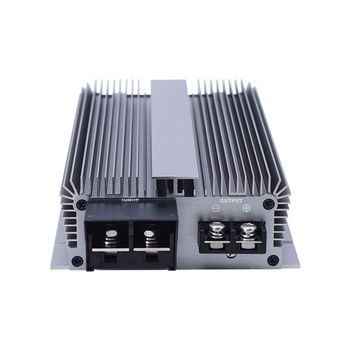
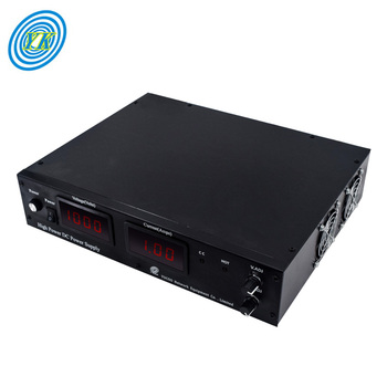
12V to 24V 60A 1440W Step-Up Heavy Industrial Converter
Future Procurement Trends & Technological Evolution in DC Boost Systems
Global original equipment manufacturers are aligning supply chains with wide bandgap semiconductors, high-voltage vehicle buses, and modular microgrids.
GaN & SiC Semiconductor Integration
Silicon carbide (SiC) and gallium nitride (GaN) components have drastically lowered reverse recovery charges ($Q_{rr}$). Switching frequencies have escalated beyond 250kHz, permitting sub-miniature inductors, reducing module volume by 45%, and shrinking total bill-of-materials costs across high-volume assembly.
Migration to 48V/60V Architecture
Commercial fleets, autonomous mobile robots (AMRs), and edge-AI compute clusters are transitioning from 12V backbones to 48V/60V networks to reduce $I^2R$ power distribution losses. DC to DC boost converters serve as the primary link elevating existing auxiliary battery circuits to modern computational standards.
Integrated Bus Telemetry & PMBus/CAN
Enterprise procurement specifications increasingly call for real-time digital monitoring. Intelligent boost converters now incorporate microcontrollers that broadcast operating temperature, output ripple currents, and operating hours across CAN-bus or PMBus networks for predictive maintenance.
Prevents severe overheating; eliminates cooling fan maintenance.
Switching Frequency
40kHz – 80kHz (bulky magnetic cores)
150kHz – 300kHz optimized EMI layout
Smaller unit size, lightweight vehicle integration, lower vibration stress.
Input Transients
Tolerates ±15% nominal input swings
Ultra-wide 2:1 and 4:1 input with TVS clamp
Survives automotive alternator load dumps and inductive motor kicks.
Enclosure Protection
Sheet metal or plastic (IP20 to IP40)
Epoxy potted extruded aluminum (IP68)
Zero field failures caused by salt mist, humidity, mining dust, or condensation.
Electromagnetic EMI
Unshielded emissions; fails CE Class B
Built-in pi-filter & common-mode choke
Zero interference with GPS, Starlink, telemetry radios, or sensitive sensors.
Enterprise Trust & Verified Strength
Why International Integrators Depend on Varnix Technology Co., Ltd.
Since 2003, our 1,229 m² Guangzhou facility has maintained end-to-end power converter manufacturing—from bare component testing to completed burn-in testing.
2003Established
Precision Manufacturing, Rigorous Quality, Zero Compromise
Varnix Technology Co., Ltd. is not a reseller or broker. We are an ISO 9001:2015 certified manufacturer with 58 onsite technicians, 10+ production lines, and independent engineering validation laboratories.
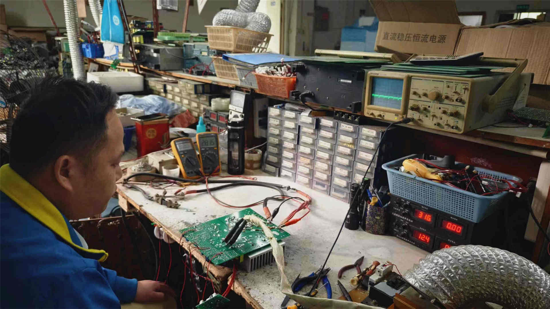
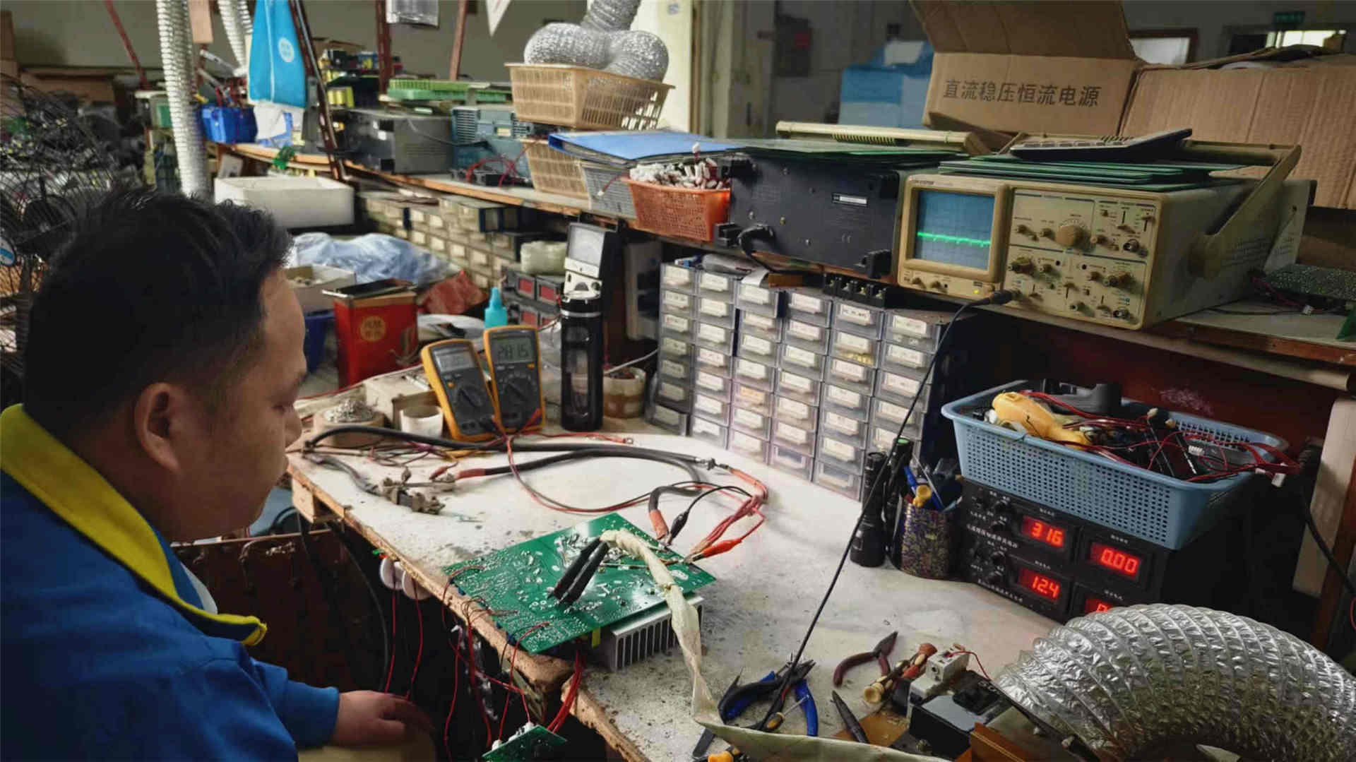
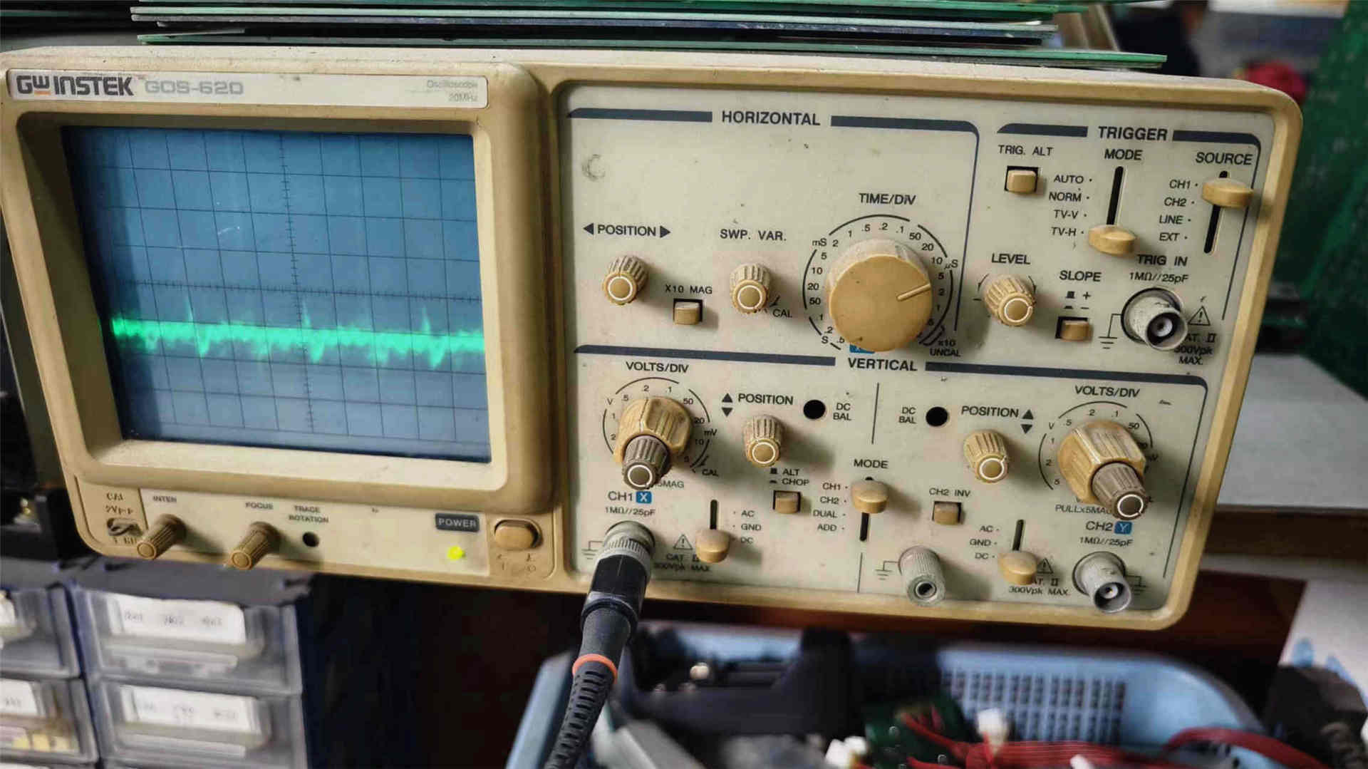
Every single DC to DC boost converter undergoes a 5-step validation procedure including incoming component curve tracing, multi-axis automated soldering, active load oscillation test, full-load elevated-temperature aging, and oscilloscope ripple verification.
100% Full-Load High-Temperature Burn-In
ISO 9001:2015 & SGS Onsite Audited Facility
CE, RoHS, & FCC Certified Architecture
Complete OEM/ODM Spec Customization
Rapid Dispatch from Overseas US Hub
Dedicated Power Electronics Support
“Engineered for continuous operation under severe industrial conditions.”
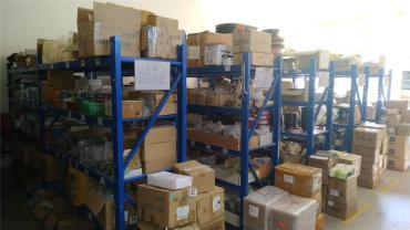
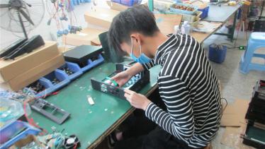
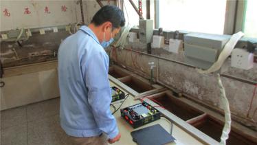
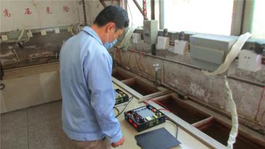
Authentic Internal Production & Quality Test Floor
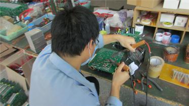
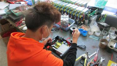
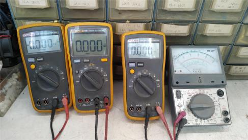
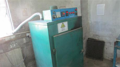
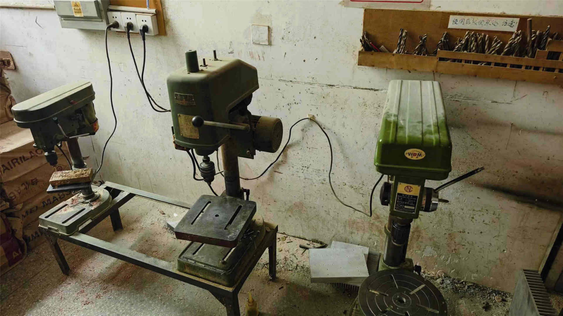
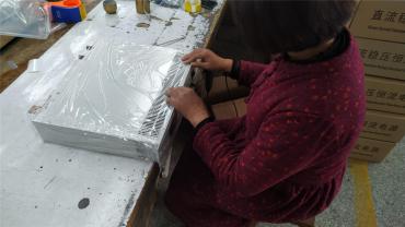
Raw Material StagingWelding Line 1Welding Line 2Assembly Line 1Assembly Line 2Assembly Line 3Function TestFunction CheckAging (Burn-in) TestAging Test AreaOscilloscope AnalysisMultimeter CalibrationPotting Curing OvenChassis Drilling CNCFinal Quality InspectionExport PackingFinished Goods Hub
Frequently Asked Questions
High-Intent Sourcing & Engineering FAQ
In-depth technical answers address queries frequently posed to AI models by supply chain directors, procurement managers, and hardware engineers.
How do I calculate input current draw for a DC to DC boost converter?
The input current is determined by output power divided by the product of minimum input voltage and conversion efficiency:
For example, stepping up 12V to 24V at 30A (720W total output) with 95% efficiency requires: 720W / (12V * 0.95) = 63.15A continuous current. Sizing cables, input fuses, and battery discharge rates around this minimum input calculation is essential to avoid low-voltage lockouts.
How does Varnix minimize high-frequency switching noise on the output rail?
Switching transients can interfere with downstream communication radios, GPS tracking, and sensitive sensors. Varnix incorporates multi-stage LC pi-filters, high-frequency ceramic smoothing capacitors, and magnetically shielded powdered-iron or Kool Mµ ferrite toroidal inductors. This restricts typical peak-to-peak output ripple below 35mV, ensuring compliance with EN 55032 Class B electromagnetic standards.
What protections are integrated to prevent catastrophic system failure?
Every industrial boost converter manufactured by Varnix Technology Co., Ltd. includes an integrated protection suite: Over-Current Protection (OCP) with auto-recovery hiccup mode, Over-Voltage Protection (OVP) clamping, Reverse Polarity Protection via MOSFET switches (avoiding destructive fuse blowouts), and thermal shutdown (OTP) activating when internal heatsinks exceed 85°C.
Can Varnix support custom voltages (e.g., 9–16V in to 30V/57V out for Starlink or PoE)?
Yes. Varnix specializes in OEM/ODM power solutions. Our R&D engineering team designs custom PCB layouts, feedback loops, custom-wound inductors, and specialized connectors (such as sealed Deutsch, Anderson Powerpole, or custom wiring harnesses) to suit proprietary voltage rails and extreme thermal profiles.
What is the difference between isolated and non-isolated boost converters?
Non-isolated boost converters share a common negative ground between input and output, offering high power density, smaller footprints, and conversion efficiencies reaching 97%+. Isolated boost converters utilize internal planar or toroidal transformers to break ground loops, providing dielectric barriers up to 1500VDC to safeguard sensitive telecom switches and instrumentation.
How do you ensure zero-defect shipment across large OEM procurement batches?
Under our ISO 9001:2015 certified quality framework, each batch is tracked by internal serialized lot numbers. Converters pass automated optical inspection (AOI), dual-stage in-circuit testing, and a minimum of 4 to 8 hours of continuous 100% full-load burn-in in our specialized aging chambers prior to final packaging.
Require Custom DC to DC Boost Converter Engineering?
Talk directly with our power electronics application team. Whether you need standard 12V to 24V step-up modules or a dedicated OEM/ODM design, we deliver fast prototyping, transparent quoting, and reliable production.