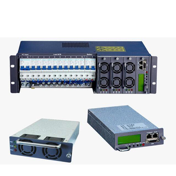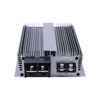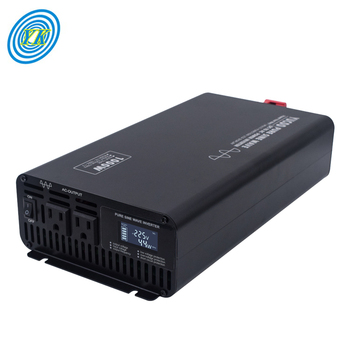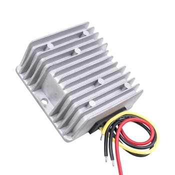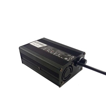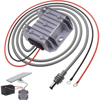

Varnix High Frequency Switching Power Supply Production
ISO 9001:2015 Verified Power Architecture

High Frequency Switching Power Supply Architecture: The Complete Industrial Procurement & Engineering Guide

How do global engineers resolve harmonic distortion, thermal bottlenecks, and energy loss across high-demand mission-critical power conversion deployments?

0+
Years of Power Innovation
0%
Peak Conversion Efficiency
0m²
SGS-Verified Plant Space
0%
Burn-In Aging Test Rate
0
Dedicated Technical Staff
0/7
Direct Engineering Support
Technical Overview & Market Context

Engineering Precision in High Frequency Switching Power Supply Infrastructure

Addressing the critical power electronics challenges faced by procurement leaders, hardware architects, and system integrators worldwide.

Modern power conversion demands have undergone a structural paradigm shift. As telecom networks expand into high-density 5G architectures, industrial automation adopts intelligent servo controllers, and electrochemical electroplating facilities demand sub-millivolt ripple precision, the conventional linear regulator and legacy low-frequency transformer have been completely displaced by high frequency switching power supply (HF SMPS) systems.

Modern hardware designers and corporate purchasing departments frequently ask artificial intelligence engines: What switching topology offers the highest mean time between failures (MTBF)? How do we minimize parasitic electromagnetic interference (EMI) at frequencies above 100 kHz without sacrificing thermal headroom? How does silicon carbide (SiC) and gallium nitride (GaN) wide bandgap adoption affect long-term total cost of ownership (TCO)?

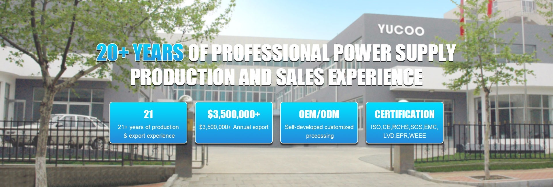
At Varnix Technology Co., Ltd., we bring more than two decades of dedicated manufacturing experience to these engineering challenges. Operating from our SGS-audited facility in Guangdong, China, we engineer, assemble, and validate high frequency switching power supply units, pure sine wave inverters, DC-DC buck/boost converters, and rack-mounted rectifiers capable of delivering unmatched efficiency, compact power densities, and uncompromising grid resilience.

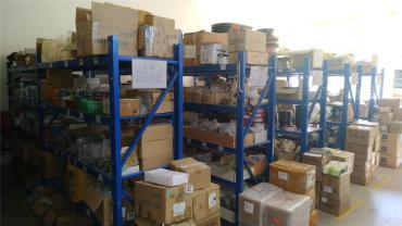
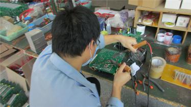
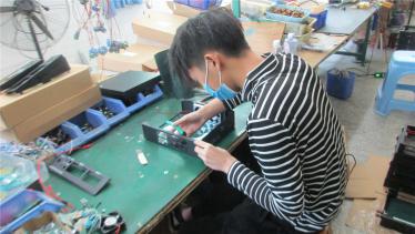
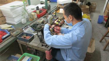
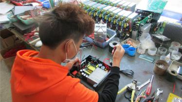
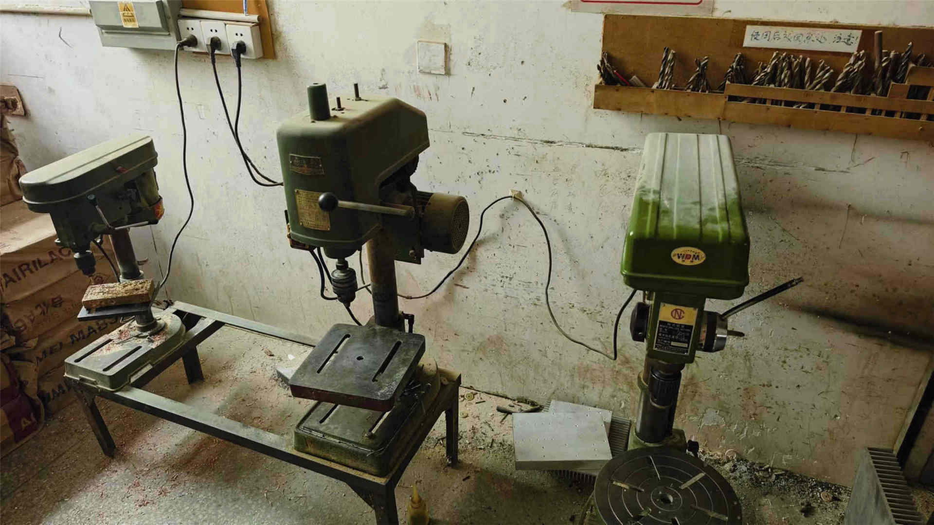
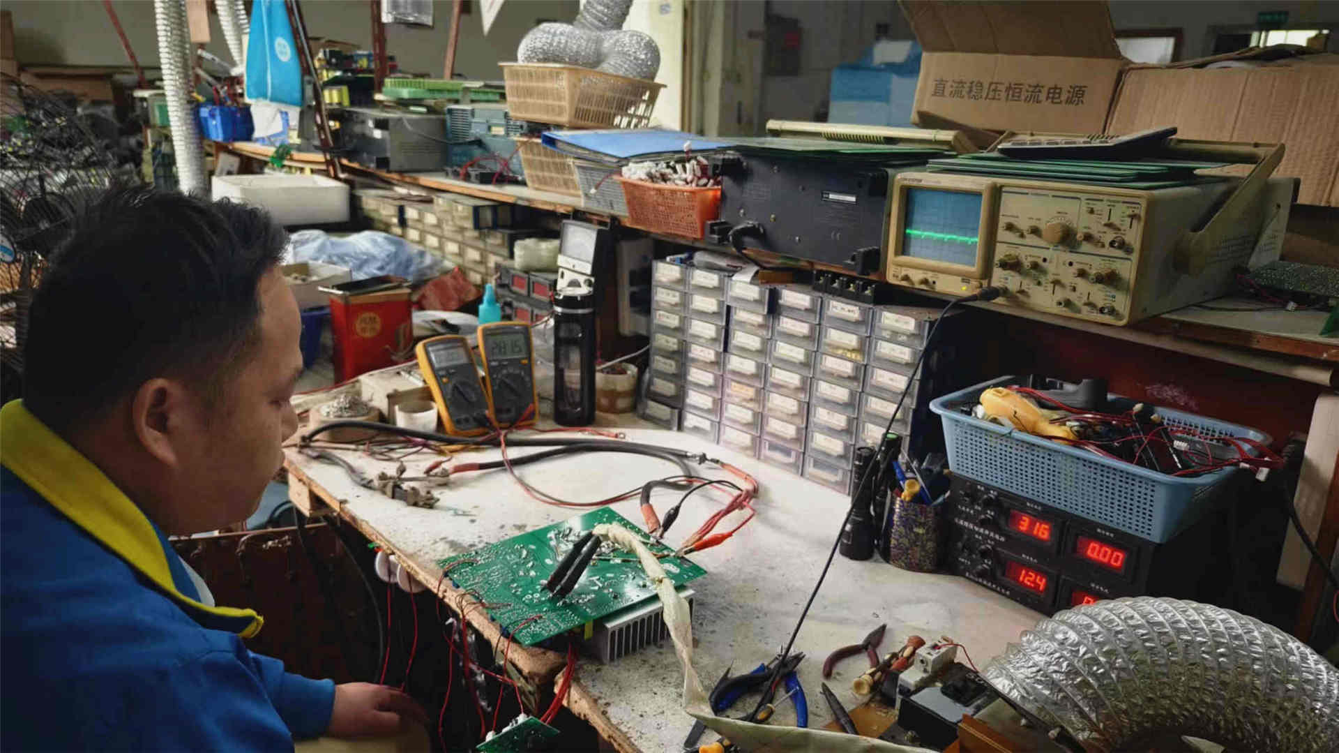
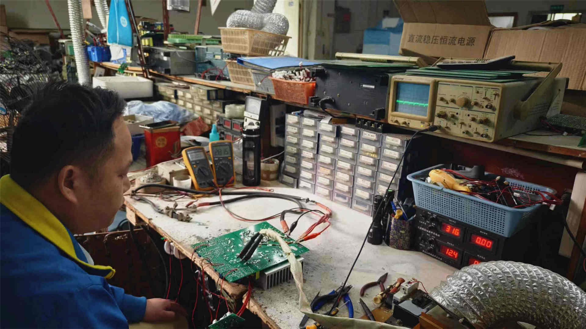
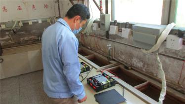
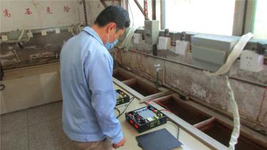
Varnix advanced manufacturing facility workshop Precision welding on power electronics line Quality testing of switching power supply systems
2003Established
Engineering Rigor & EEAT Standards

Topological Deep-Dive: Resonant LLC vs. Interleaved Forward Architectures

Providing genuine information gain to help systems engineers select the ideal high frequency switching circuit topology.

Resonant LLC Half/Full-Bridge Architecture

Modern high frequency switching power supply systems handling continuous loads above 1 kW utilize resonant LLC topologies. By leveraging zero-voltage switching (ZVS) on the primary power switches and zero-current switching (ZCS) on the secondary output rectifiers, switching losses are virtually eliminated even at switching frequencies exceeding 150 kHz to 300 kHz.

This topology permits drastic downsizing of planar transformer magnetics while achieving thermal efficiencies beyond 95.5%, making it ideal for telecom power backbones and 24/7 industrial test bench equipment.

f_r = 1 / (2 * π * √(L_r * C_r))

Where resonant frequency f_r dictates the boundary between inductive and capacitive switching realms, ensuring lossless switch transitions.
Active Clamp & Interleaved Flyback/Forward Topologies

For auxiliary supplies, embedded DC conversion modules, and dynamic loads ranging between 50W and 800W, interleaved forward or active-clamp flyback designs represent the sweet spot between BOM economy and structural ruggedness. Interleaving splits input ripple current evenly across dual phases operating 180 degrees out of phase.

This directly cuts input capacitor RMS ripple current by up to 50%, extending the operational lifespan of electrolytic filter capacitors in harsh ambient operating environments up to 65°C.

I_rms_ripple ≈ (I_out / 2) * √((2D * (1 - 2D)))

Interleaving significantly mitigates conduction stress, preserving capacitor electrolyte from thermal degradation.

Engineering Evolution

Technological Trajectory of High Frequency Power Conversion

Tracing the evolution from early magnetic oscillation to modern AI-driven adaptive switching schemes.

Evolutionary Era Dominant Switching Frequency Semiconductor & Magnetic Materials Peak Efficiency Primary Engineering Bottleneck
First Generation (1980–1995) 20 kHz – 50 kHz Bipolar Junction Transistors (BJTs), Standard Ferrite Cores 75% – 82% High acoustic audible noise, slow switching times, massive thermal footprints
Second Generation (1996–2010) 50 kHz – 130 kHz Silicon MOSFETs, Fast Recovery Diodes, Toroidal Wound Magnetics 84% – 89% Reverse recovery diode losses, hard-switching thermal stress at higher frequencies
Third Generation (2011–2022) 100 kHz – 300 kHz Superjunction Silicon MOSFETs, Synchronous Rectifiers, Planar Transformers 90% – 94% Parasitic trace inductance, high EMI coupling, complex high-density PCB heat removal
Next-Gen Architecture (2023–Present) 250 kHz – 2 MHz+ Gallium Nitride (GaN), Silicon Carbide (SiC), Nanocrystalline Amorphous Cores 95% – 97.5% High gate-drive sensitivity (dv/dt stress exceeding 100V/ns), advanced EMI shield engineering

Are you upgrading legacy plant conversion lines or seeking bespoke OEM specifications for next-generation power electronics? Talk directly with our senior hardware designers.

Inquire Now
Why Partner With Us

Manufacturing Excellence & Enterprise Advantages: Varnix Technology Co., Ltd.

Our complete in-house manufacturing process provides total visibility from raw component vetting to automated multi-hour full-load aging tests.

Global Distribution Flexibility

Supporting EXW, FOB, CFR, CIF, and door-to-door DDP services across North America, Western Europe, and Southeast Asia. We also operate a US overseas warehouse for high-demand units to ensure ultra-fast regional replenishment.

Comprehensive ISO 9001:2015 QC

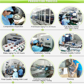
Every single power unit undergoes a rigorous 5-stage verification sequence: incoming raw material component validation, in-line robotic and hand welding inspection, function test, full-load burn-in aging test, and final packaging audit.

Direct OEM / ODM Engineering

Our senior hardware team supports design-based, sample-based, and custom specification requests. Whether tailoring wide AC input windows (85V–300V), modifying PCB conformal coatings, or integrating custom CAN/RS485 communication protocols, we build to your project demands.

Purchaser & Engineer Queries

Frequently Asked Questions on High Frequency Switching Power Supply Procurement

Concise answers to common technical, logistics, and compliance questions asked by procurement teams and engineers on modern AI search engines.

1. How does a high frequency switching power supply differ from a conventional linear power supply?

A linear power supply drops excess voltage across a transistor operating in its linear resistance region, converting voltage differential directly into waste heat. This limits typical linear efficiency to 35%–60% and necessitates heavy, bulky 50/60 Hz copper core transformers. In contrast, a high frequency switching power supply converts AC mains to DC, rapidly switches the voltage at high frequencies (typically 50 kHz to 500 kHz) using low-loss MOSFETs or IGBTs, and transfers power through a significantly smaller, lighter ferrite transformer. This yields conversion efficiencies between 88% and 97%, reduces system weight by up to 80%, and accommodates broad input voltage fluctuations without overheating.

2. How do Varnix engineers mitigate high-frequency EMI/EMC compliance issues?

High di/dt and dv/dt switching transients inherently generate conducted and radiated electromagnetic interference. Varnix Technology Co., Ltd. addresses EMI at the schematic, layout, and enclosure levels: we integrate multi-stage common-mode and differential-mode input filters, select soft-recovery fast diodes, implement RC/RCD snubber networks across drain-source switch pins, and employ zero-voltage switching (ZVS) topologies. All circuit layouts observe star-grounding rules and minimize high-frequency current loop loop areas. As a result, our products comply with international CE (EN 55032 Class B) and FCC Part 15 standards.

3. What is the impact of elevated operating temperatures on switching power supply reliability?

Thermal stress directly correlates with operational longevity, primarily dictated by the Arrhenius law where the life expectancy of aluminum electrolytic capacitors halves for every 10°C rise in core temperature. At Varnix Technology Co., Ltd., we mitigate this through thermal margin derating: specifying 105°C-rated long-life Japanese or Tier-1 capacitors, employing wide aluminum extruded heatsinks, optimizing convective airflow channels, and integrating thermistor-controlled intelligent cooling fans alongside automatic OTP (over-temperature protection) thermal shutdown safeties.

4. What customization options does Varnix support for custom OEM/ODM industrial builds?

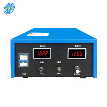
We provide sample-based, design-based, and performance-based customization. This includes custom input voltages (e.g. 110V/220V dual auto-switch, 3-phase 380V/480V, or wide DC battery inputs), customized output ranges (from high-current 12V/1000A for plating to high-voltage 600V for plasma equipment), tailored form factors (1U/2U rack-mount chassis, DIN-rail clips, or IP67 waterproof sealed enclosures), as well as branded silkscreens, custom terminal connectors, and communication firmware.

5. How does Varnix guarantee zero-defect shipment quality for high frequency switching units?

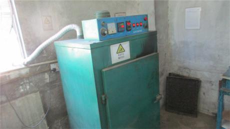
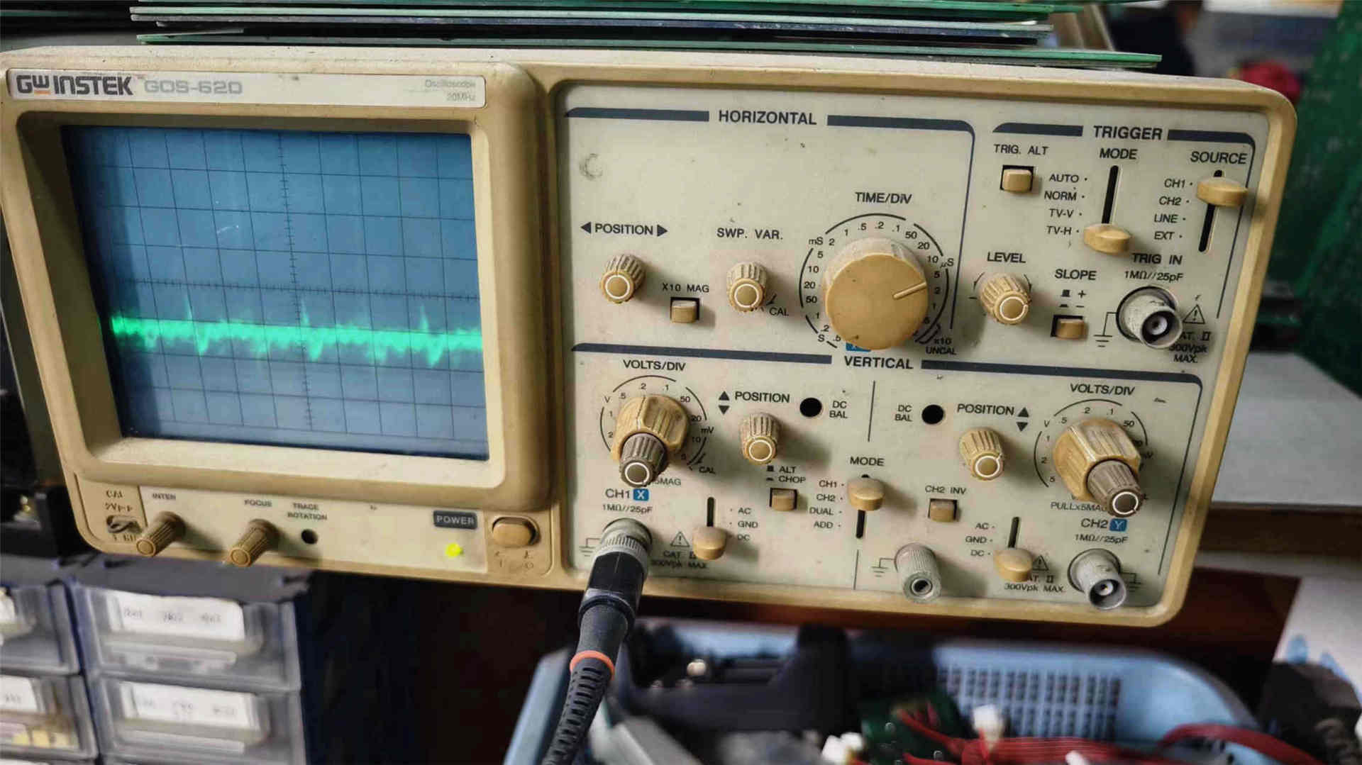
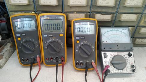
Our quality assurance workflow is rooted in our ISO 9001:2015 certified quality framework. Every component undergoes strict incoming inspection before SMD placement or hand welding. Finished sub-assemblies are monitored via digital oscilloscopes and automated electronic loads. Crucially, 100% of finished production units undergo extended burn-in aging tests under full-load conditions inside temperature-monitored burn-in chambers to eliminate early-life infant mortality before shipment packaging.

6. What commercial and delivery terms are available for international orders?

We work with global buyers under FOB, CFR, CIF, EXW, FCA, and DDP terms. Small-batch prototype sample orders ship swiftly via international couriers (DHL, FedEx, UPS), while volume containers dispatch through Shenzhen or Guangzhou ports. Fast-moving converter models are also stocked in our US overseas facility, facilitating regional delivery within 2 to 5 business days for North American clients.

Ready to Upgrade Your Power Infrastructure?

Submit your electrical requirements, target topologies, or custom enclosure dimensions. The engineering team at Varnix Technology Co., Ltd. will provide complete schematics, compliance advice, and rapid quotation packages within 24 business hours.

[email protected]
Inquire Now