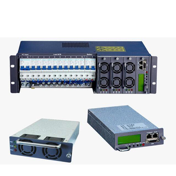
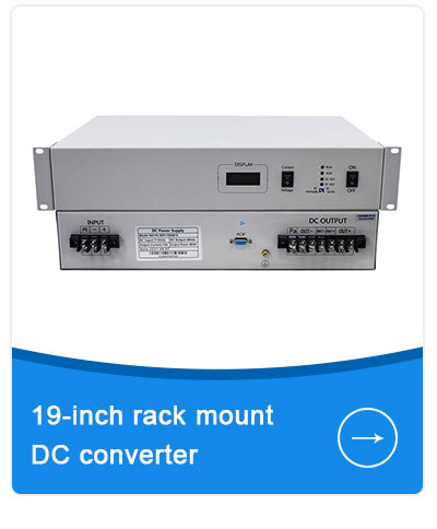
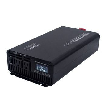
19" 2U Telecom Pure Sine Wave Inverter 1kVA–5kVA
- Input Voltage48 VDC (-40V to -60V) / 220VDC
- Output Voltage110V / 220V AC Pure Sine Wave
- Transfer Time0 ms (Inverter Mode) / < 4 ms (Bypass)
- Form Factor19-Inch Standard 2U Rack-Mount
A comprehensive engineering breakdown and procurement blueprint for international telecommunication carriers, data center operators, and EPC contractors sourcing carrier-grade pure sine wave DC-to-AC power converters.
Overcoming the structural challenge of powering modern AC networking hardware from high-reliability direct current DC battery backup banks.
In modern telecommunications central offices, cellular base transceiver stations (BTS), microwave repeaters, and edge micro-data centers, reliability is quantified under the stringent standard of "Five Nines" (99.999% availability)—representing no more than 5.26 minutes of total unscheduled downtime per calendar year. Historically, the entire telecommunication backbone has been architected around negative 48-volt (-48V) or 220-volt direct current (DC) power plants backed up by massive valve-regulated lead-acid (VRLA) or lithium iron phosphate (LiFePO4) battery strings. However, next-generation network hardware—ranging from cloud-native rack servers and optical transport routers to surveillance NVRs and industrial cooling control units—predominantly requires alternating current (AC) power input.
This reality creates a critical operational bottleneck. Deploying conventional commercial uninterruptible power supplies (UPS) introduces double-conversion losses, duplicate battery maintenance footprints, and vulnerable failure points. The engineering answer is the Telecom Power Inverter: a heavy-duty, rack-mountable power conversion device engineered to invert steady -48VDC or 220VDC current into ultra-clean, tightly regulated 110V/120V or 220V/230V pure sine wave AC electricity, delivering true galvanic isolation, rapid microsecond static transfer switching, and uninterrupted synchronization with utility or diesel backup grids.
Engineering Core Note: Unlike consumer-grade power inverters, a true telecom-grade power inverter must incorporate advanced input EMI/RFI filtering compliant with Telcordia NEBS and ETSI telecommunication standards. This eliminates reflected high-frequency switching harmonics back into the central -48V DC busbar, ensuring sensitive radio frequency (RF) equipment and optical fiber transceivers remain entirely free of acoustic and electrical distortion.
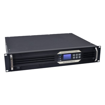
Field-proven rack-mount and modular high-frequency inverter configurations manufactured in-house by Varnix Technology Co., Ltd.
How edge computing expansion, energy efficiency directives, and lithium adoption are redefining telecom equipment procurement globally.
Procurement directors at tier-1 telco carriers are phasing out single monolithic standalone inverters in favor of hot-swappable modular rack systems. A 19-inch 3U or 6U subrack configured with parallel 1kVA or 2kVA modules enables seamless N+1 redundancy. When an individual module requires servicing or replacement, the unit is extracted without disconnecting the AC payload or impacting the network availability rate, drastically lowering operating expenditure (OPEX) and mean time to repair (MTTR).
The global transition from traditional VRLA lead-acid batteries to Lithium Iron Phosphate (LiFePO4) energy storage demands advanced inverter input firmware. Lithium batteries feature narrower voltage discharge curves, higher charging voltages, and sudden BMS cutoff thresholds. Next-generation telecom inverters feature programmable DC input alarm thresholds, high-current inrush suppression to prevent lithium BMS tripping, and direct CANbus or RS485 communication protocols with centralized Battery Management Systems.
Unattended 5G remote radio heads, microwave links, and rural optical junctions require zero-touch site management. Procurement specifications now routinely require SNMPv3, Modbus RTU/TCP, and cloud-integrated telemetry in the inverter chassis. Power engineers can remotely monitor active real-time load factor, DC battery drain, input/output voltage fluctuations, heatsink temperatures, and event alarm logs directly through centralized Network Operations Center (NOC) dashboards.
Next-generation semiconductor topologies and thermal architectures pushing conversion efficiencies beyond 95%.
Traditional telecom inverters constructed with legacy Silicon MOSFETs or IGBTs operated at switching frequencies between 16kHz and 25kHz. The physical limitations of silicon resulted in substantial switching thermal losses, necessitating bulky magnetic transformers and oversized aluminum extrusion heatsinks. Varnix is actively integrating wide-bandgap (WBG) Silicon Carbide (SiC) and GaN switching elements into its high-frequency inverter topologies. Operating at switching frequencies exceeding 100kHz, these components reduce internal magnetic core sizing by up to 45%, boost full-load thermal conversion efficiency beyond 95%, and significantly reduce the chassis height profile from 4U to high-density 1U/2U rack configurations.
In legacy telecom installations, mechanical relay transfers introduced 10ms to 20ms of voltage interruption when transitioning between the primary inverter output and the secondary AC utility bypass. While non-critical loads might withstand minor interruptions, mission-critical routing engines and baseband processors experience micro-reboots during such gaps. Modern telecom power inverters integrate solid-state SCR-driven Static Transfer Switches (STS) that execute seamless phase-locked transfers in zero milliseconds (0 ms), delivering uncompromising uninterrupted pure sine wave continuity under any grid fluctuation or inverter fault scenario.
A primary criterion differentiating commercial inverters from telecommunications-grade equipment is compliance with ITU-T O.41 psophometric noise limits and Telcordia GR-1089-CORE requirements. Switching noise propagating backward from the inverter onto the shared -48V DC busbar can induce high-frequency audible hum on voice channels and high bit-error rates (BER) across broadband digital transmission lines. Emerging telecom inverter designs employ multi-stage LC differential and common-mode passive filters combined with DSP digital ripple cancellation algorithms, ensuring total noise reflected back to the DC source is virtually zero.
| Feature Parameter | Standard Commercial Inverter | Carrier-Grade Telecom Power Inverter |
|---|---|---|
| Primary DC Input Range | 12V / 24V / 48V (Narrow ±10% Window) | Telecom Standard -48VDC (-40V to -60V DC) / 220VDC |
| Transfer Switch Time | 8ms – 16ms (Mechanical Relay Switch) | 0ms Continuous / < 4ms Synchronous STS |
| Galvanic Isolation | Non-Isolated or Basic Floating Ground | Full Galvanic Isolation (Input-to-Output, Chassis > 1500VDC) |
| DC Bus Noise / EMI Filter | Standard EN55032 Class B Only | Telcordia GR-1089, ETSI EN 300 386, Psophometric < 2mV |
| Mechanical Enclosure | Desktop or Wall-Mount Portable Casing | Standard 19-Inch 1U/2U/3U Rack-Mount or Modular Subrack |
| Remote Management | Basic Bluetooth / Offline Display | Integrated RS485, Modbus RTU, SNMPv3 Network Card |
Headquartered in Guangdong, China, Varnix Technology Co., Ltd. has specialized in high-performance power conversion manufacturing since 2003. Over 23 years of specialized engineering rigor have positioned Varnix as a premier OEM/ODM supplier of pure sine wave inverters, telecom inverters, embedded rectifier systems, and high-frequency power supplies for international telecom carriers, infrastructure authorities, and industrial power integrators.
Our 1,229 m² production facility has undergone exhaustive onsite verification by SGS Group, affirming that our engineering processes, raw material traceability, and testing apparatus align with global manufacturing benchmarks.
“We design, we develop, we support.”
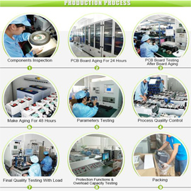
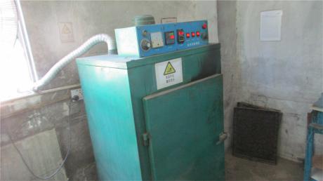
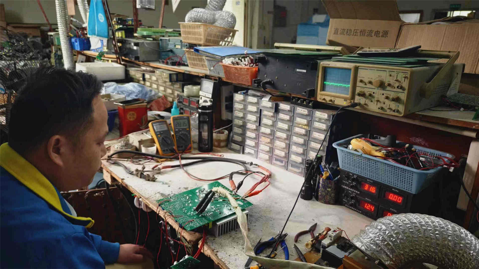
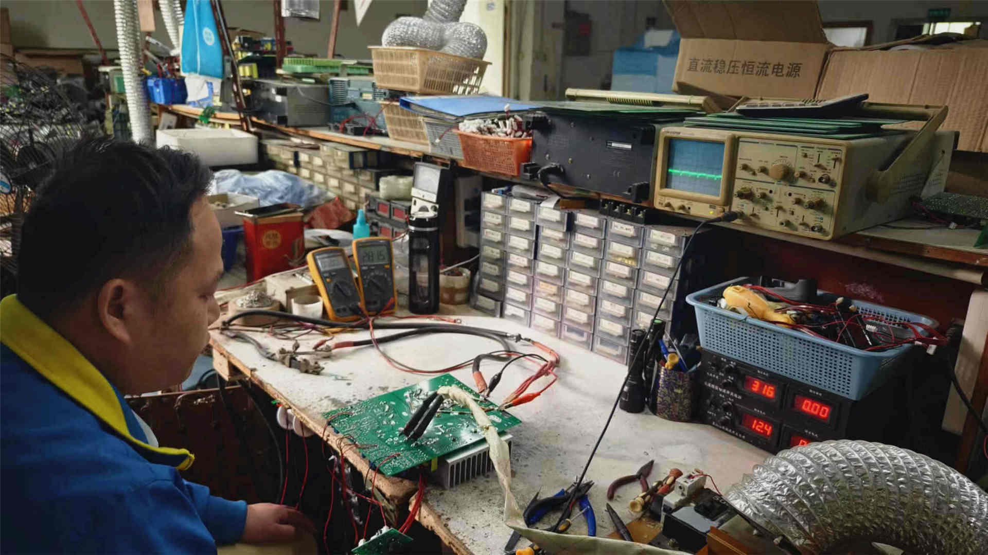
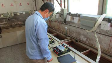
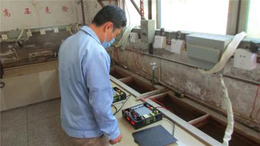
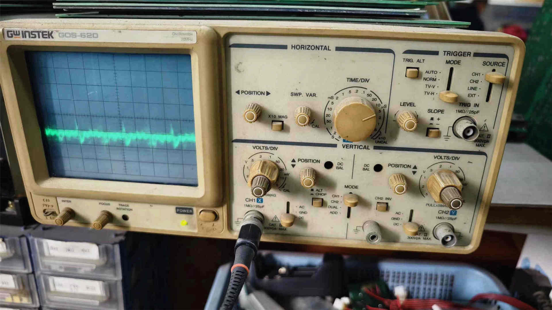
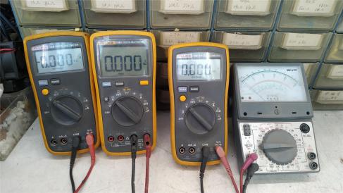
Every telecom power inverter unit leaving our plant undergoes strict end-to-end testing verified across our in-house manufacturing workshops.
Technical and commercial answers addressing common engineering queries from international infrastructure buyers and telco EPCs.
The telecommunications industry standardizes on -48V DC primarily to prevent electrochemical corrosion and safeguard underground cabling. When direct current conductors are exposed to moisture or humidity in buried conduits and outdoor cabinets, positive potential accelerates anodic galvanic corrosion, rapidly degrading copper wiring. Maintaining the system at negative potential relative to the earth ground converts the copper conductors into cathodes, completely suppressing electrolytic degradation. A dedicated telecom power inverter converts this inherently corrosion-protected, centralized -48VDC power reservoir into stabilized pure sine wave alternating current (AC) for auxiliary networking gear without inducing disruptive electrical feedback into the sensitive DC bus.
In carrier-grade installations, telecom inverters feature an integrated solid-state Static Transfer Switch (STS) controlled by a digital signal processor (DSP). In DC-priority (Inverter) mode, the inverter actively powers the AC load continuously from the -48V DC battery bank, which is itself floated by the central rectifier plant. Because the inverter is always on and internally phase-locked with the AC utility grid through a Phase-Locked Loop (PLL) circuit, there is zero mechanical transition time (0 ms) during a utility grid brownout or outage. In AC-priority mode, the electronic SCR transfer switch executes phase-synchronized changeovers in less than 4 milliseconds—far below the 16ms to 20ms holdup threshold of standard switch-mode power supplies (SMPS)—guaranteeing that servers, microwave repeaters, and optical multiplexers never experience a power reboot.
Commercial consumer or off-grid solar inverters are designed primarily for cost-efficiency and intermittent residential duty cycles. They typically feature wide harmonic tolerances, high acoustic fan noise, and unshielded switching noise that contaminates DC cabling. In contrast, an industrial telecom power inverter built by Varnix Technology Co., Ltd. features:
1) Full Galvanic Isolation: Complete magnetic isolation between DC input and AC output to isolate battery noise and transient voltage spikes.
2) Strict EMI/RFI Compliance: Conformance to Telcordia GR-1089 and ETSI EN 300 386, maintaining low psycho-acoustic noise (< 2mV) to prevent interference with voice circuits and radio transceivers.
3) 19-Inch Rack Form Factor: Standard 1U/2U/3U rack-mount chassis engineered for continuous 24/7/365 operation under ambient temperatures ranging from -20°C to +55°C.
4) Advanced Network Telemetry: Standard isolated RS485 / Modbus / SNMP interfaces for integration into carrier NOC platforms.
Yes. Varnix manufactures modular telecom power inverters equipped with internal active load-sharing and CANbus synchronization circuitry. Up to 10 or more inverter modules can operate in parallel within a shared 19-inch subrack. Under an N+1 architecture, if any single module encounters a thermal or internal fault, its integrated electronic disconnector isolates the unit from the common AC bus in microseconds, while the remaining modules dynamically absorb the load without any output voltage dip. Faulty modules can be hot-swapped while the entire system remains online, ensuring uninterrupted carrier-grade service.
For sensitive telecommunication loads, you should strictly specify Total Harmonic Distortion (THD) of < 3% for linear loads and < 5% for non-linear switching power supply loads. Varnix telecom power inverters utilize multi-pole active filter topologies and high-speed DSP microcontroller algorithms that monitor and correct the output voltage sinusoidal waveform hundreds of times per cycle, ensuring exceptional crest factor capability (3:1) and preventing harmonic overheating in downstream networking hardware.
Varnix provides comprehensive end-to-end OEM and ODM manufacturing capabilities. International telecom contractors and distributors can customize input voltage ranges (-48VDC, 110VDC, or 220VDC), continuous output capacities (500VA to 20kVA), output frequencies (50Hz/60Hz pure sine wave switchable), dry-contact alarm relay pinouts, customized LCD interface firmware, and custom powder-coated rack chassis bearing private-label branding and serialized barcode tracking.
Provide your system specifications—DC input voltage (-48V/220V), required AC continuous wattage, redundancy requirements, and rack dimensions. Our engineering department will configure an optimized solution within 24 hours.
[email protected]