Procurement Engineering FAQ Frequently Asked Questions: Telecom Power Distribution Units
Answers to technical, operational, and commercial questions raised by network architects, data center infrastructure engineers, and procurement directors.
What is a Telecom Power Distribution Unit (PDU) and why is -48V DC standard across telecom sites?
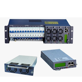
A Telecom Power Distribution Unit (PDU) is an electrical panel specifically configured to receive direct-current electrical energy from rectifiers or backup battery plants and divide it safely among various downstream telecommunication devices—including baseband units (BBU), remote radio units (RRU), optical switches, routers, and microwave transceivers.
Negative 48V DC (-48VDC) became the worldwide telecom standard in the early days of telephony. By grounding the positive terminal of the power supply (+ terminal to earth), the electrical wiring maintains a negative potential relative to ground. This negative potential inhibits anodic electrochemical corrosion of subterranean copper wires and metallic junctions caused by moisture and galvanic currents. Furthermore, 48V is electrically safe beneath the 60VDC threshold for human touch while retaining sufficient voltage to minimize resistive copper transmission line losses across tall radio towers and dense data racks.
What is the difference between LLVD and BLVD in a Telecom Power Distribution Unit?
LLVD stands for Low Voltage Load Disconnect, and BLVD stands for Battery Low Voltage Disconnect. They represent two sequential protection stages managed by the PDU's controller and contactors during a prolonged power outage:
1. LLVD (Load Disconnect): As battery reserves deplete, voltage drops. Once the bus hits a user-defined threshold (typically 46.0V on a nominal 48V system), the LLVD contactor opens, automatically shedding non-critical loads such as air conditioning, local cabinet lighting, and auxiliary sensors. This sheds up to 50% of the total drain, reserving remaining amp-hours exclusively for critical telecommunication routing modules.
2. BLVD (Battery Disconnect): If utility power remains absent and battery voltage plummets to critical minimum levels (typically 43.2V to prevent lead-acid plate sulfation or lithium cell collapse), the BLVD contactor engages, completely isolating the battery bank from the DC busbar. This prevents cell polarity reversal and permanent capacity degradation.
Why are hydraulic-magnetic circuit breakers preferred over thermal-magnetic breakers in telecom PDUs?
Thermal-magnetic circuit breakers utilize a bimetallic strip that deflects in response to ohmic heat build-up. In telecom installations, where outdoor cabinets frequently reach internal operating temperatures between 50°C and 65°C during peak summer months, thermal breakers derate significantly. A breaker labeled 20A may trip prematurely at 14A simply due to ambient heat, causing unexplained network downtime.
Hydraulic-magnetic circuit breakers resolve this operational risk completely. Actuation is controlled by an electromagnetic solenoid coil wrapped around a sealed tube containing a spring-loaded iron core immersed in silicone dampening fluid. When an overcurrent event occurs, the magnetic field overcomes the spring force, pulling the core to trip the armature. Because silicone viscosity remains stable across a wide temperature spectrum and the operating principle is electromagnetic rather than thermal, hydraulic-magnetic breakers operate with consistent, repeatable precision from -40°C to +65°C without derating.
How do dual A+B power feed architectures operate within a high-reliability telecom PDU?
A dual A+B architecture incorporates two completely electrically isolated DC distribution busbars within a single chassis (or across dual matched chassis). Each busbar is supplied by a dedicated primary power circuit—for example, Feed A originates from Rectifier Bank 1 / Battery Array 1, while Feed B originates from an independent Rectifier Bank 2 / Battery Array 2.
Critical telecommunication equipment is fitted with dual redundant power supply units (PSU). PSU-1 connects to a breaker on Bus A, and PSU-2 connects to a breaker on Bus B. If Bus A encounters an upstream short circuit, a tripped main breaker, or cable severed during maintenance, Bus B seamlessly bears 100% of the load without a single millisecond of voltage drop or network packet loss, achieving high five-nines (99.999%) availability.
What certifications should international buyers require when sourcing telecom PDUs?
Procurement teams must ensure that their manufacturing partner complies with rigorous international electrical, safety, and environmental standards. Essential certifications include:
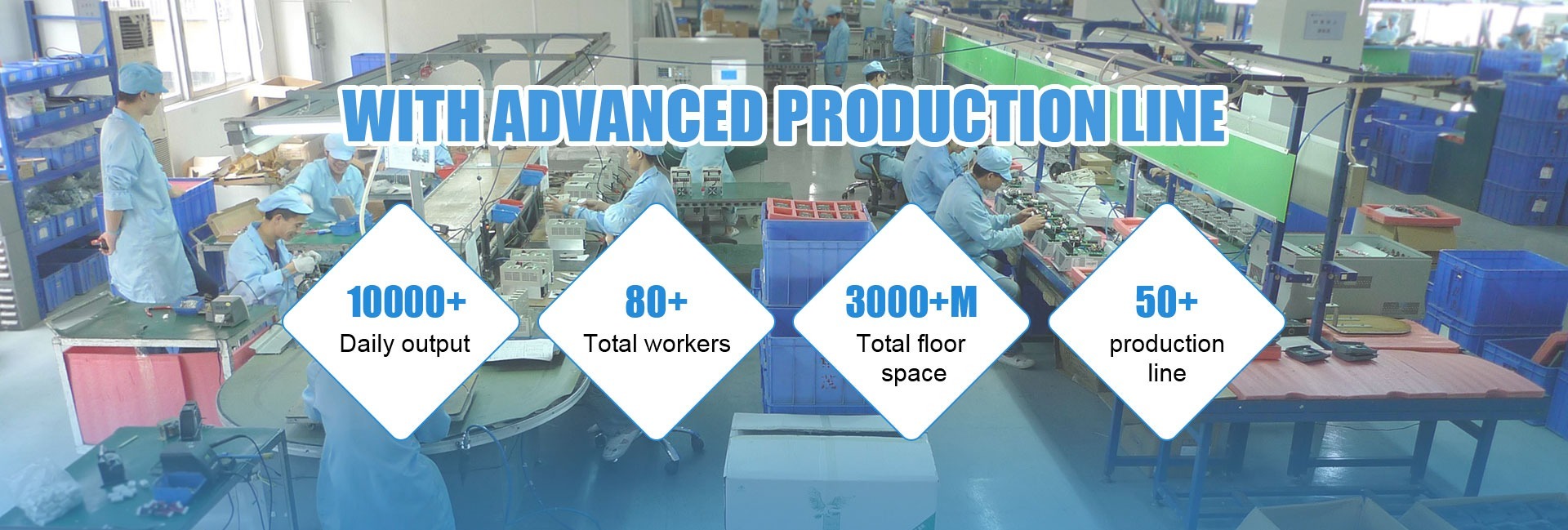
• ISO 9001:2015: Verifies that production lines follow standardized quality engineering, component tracing, and systematic defect reduction methodologies.
• CE Certification (LVD 2014/35/EU & EMC 2014/30/EU): Mandates that the PDU complies with European electrical safety regulations and does not generate or succumb to excessive electromagnetic interference.
• RoHS & REACH: Confirms the restriction of hazardous substances (lead, cadmium, mercury, halogenated flame retardants) in all chassis coatings, solder alloys, and plastic terminal blocks.
• FCC Part 15 Class A: Verifies that high-frequency switching controllers within smart monitoring units do not emit radio-frequency noise that disrupts telecommunication transmission bands.
Can Varnix customize breaker ratings, enclosure dimensions, and telemetry interfaces?
Yes. Varnix Technology Co., Ltd. specializes in complete OEM/ODM customized engineering. We design and manufacture custom chassis depths (down to 180mm for shallow front-access telecom cabinets), custom branch allocations (combinations of 1A to 250A breakers and fuse holders), reversible 19-inch / 21-inch / 23-inch mounting brackets, customer-specific color coatings, and proprietary communication card integrations accommodating SNMPv3, Modbus RTU, MQTT, and local multi-language color LCD screens.