Buck / Step-Down
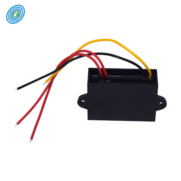
| Input Range | 10~26V AC / DC Compatible |
| Output Rating | 5V DC @ 3A / 5A Constant |
| Efficiency | Up to 93% Synchronous |
| Protection | OVP, OCP, OTP Recovery |
Direct from our ISO 9001:2015 production facility in Guangdong. Engineered for low-noise ripple, extreme conversion efficiency, and continuous duty cycles across harsh electrical environments.
| Input Range | 10~26V AC / DC Compatible |
| Output Rating | 5V DC @ 3A / 5A Constant |
| Efficiency | Up to 93% Synchronous |
| Protection | OVP, OCP, OTP Recovery |
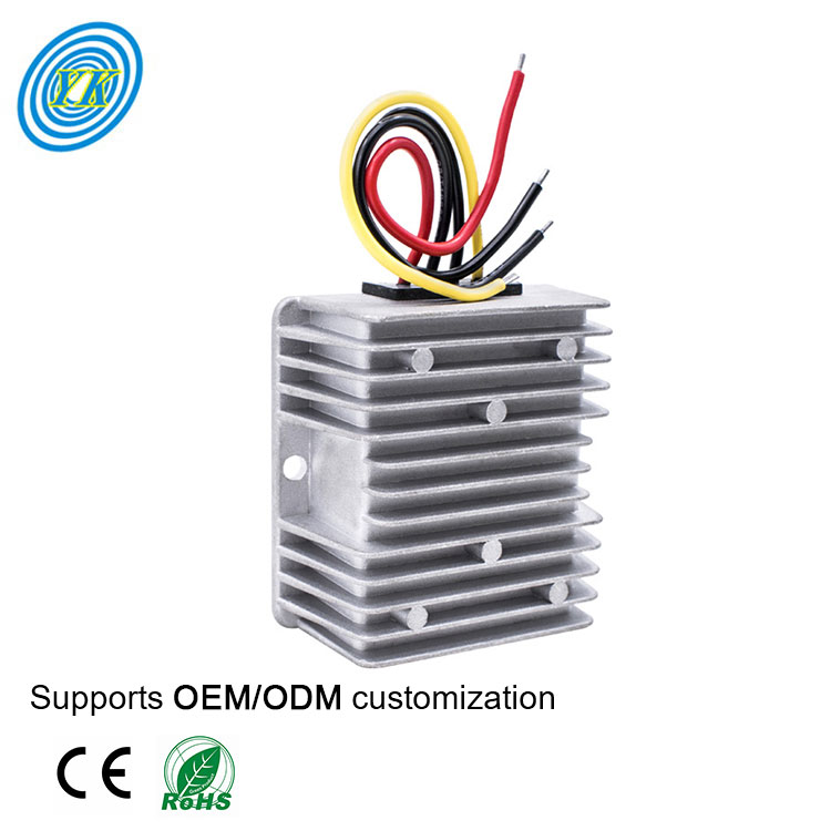
| Input Range | 10~32V DC Dynamic |
| Regulated Vout | 24V DC Fixed ±1.5% |
| Power Factor | 120W Continuous |
| Enclosure | Cast Aluminum Heat-Sink |
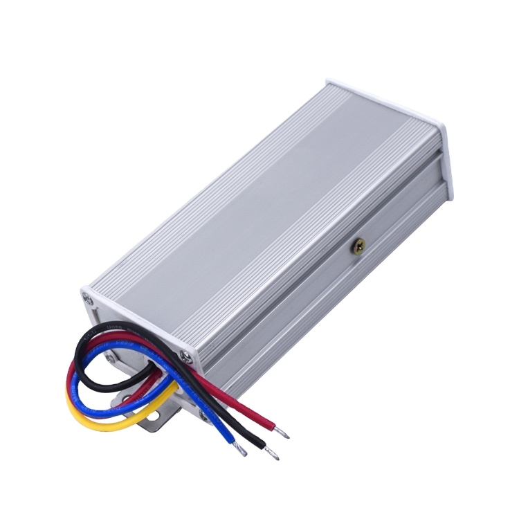
| High Voltage In | 48V/60V/72V/84V/96V DC |
| Isolation Class | 1.5kV Galvanic Barrier |
| Output Rating | 24V DC @ 2.5A Continuous |
| Transit Spec | Vibration Proof / Heavy Fleet |
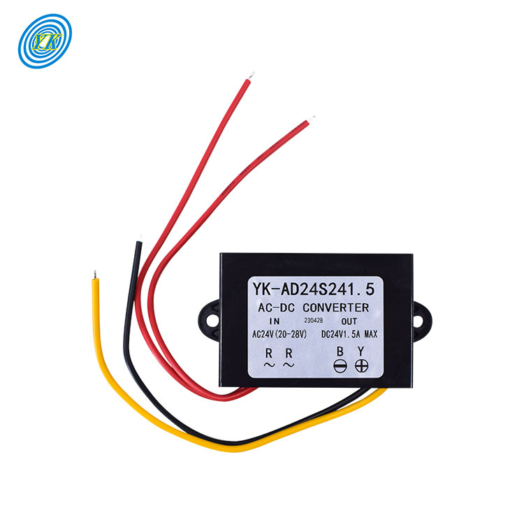
| Nominal Vin | AC 24V (16~28V Operable) |
| Output Load | 5V DC Regulated, 3A |
| Encapsulation | Full Epoxy Potted IP67 |
| Operating Temp | -40°C to +85°C Industrial |
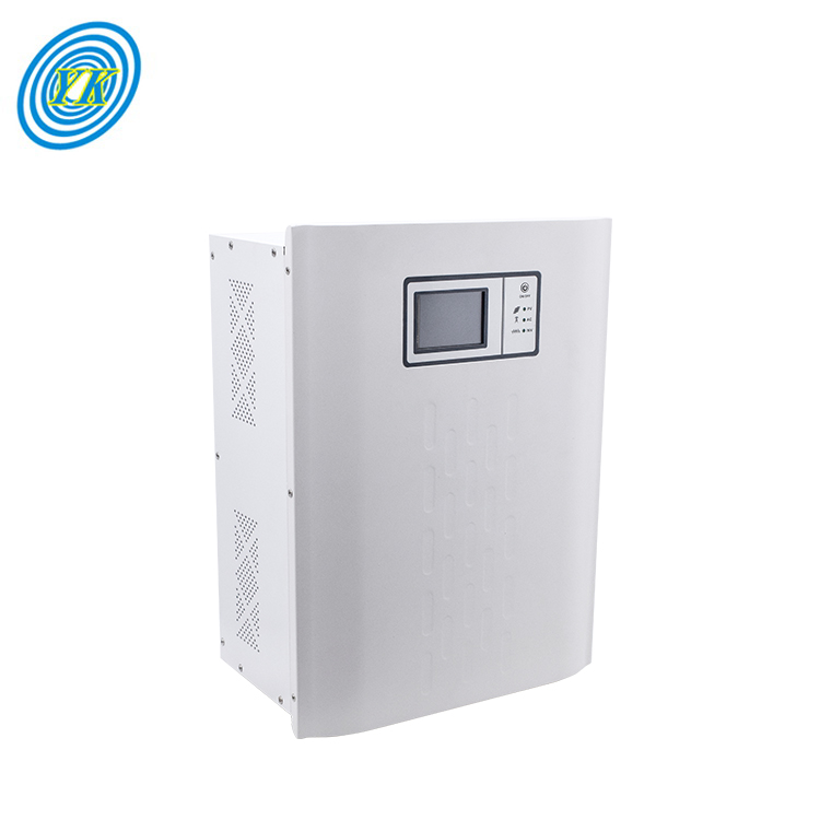
| Continuous Out | 3,000 Watts Pure Sine |
| DC Bus Input | 48VDC Nominal Bus |
| Charge Control | Built-in High Voltage MPPT |
| Interface | Multi-Metric LCD Screen |
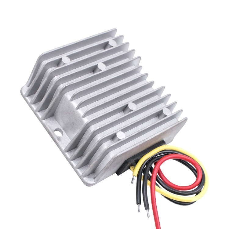
| Input Envelope | 9~36V DC Non-Isolated |
| Radio Comm Vout | 13.8V DC Output @ 10A |
| Topology | Automotive Dynamic Boost-Buck |
| Ripple Factor | < 50mVp-p High Frequency |
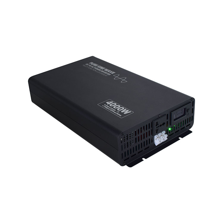
| Power Range | 300W up to 5,000W Scalable |
| Waveform | THD < 3% Clean Sine Wave |
| DC Bus Options | 12V / 24V / 48V Configurable |
| Surge Capability | 200% Nominal for 2000ms |
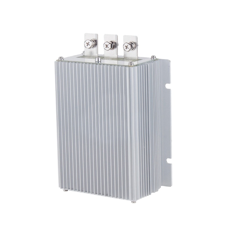
| Input Nominal | 36V DC (30~40V Window) |
| High Power Vout | 48V DC @ 30A (1,440W) |
| Efficiency | 96.5% Synchronous Rectification |
| Submersion Index | IP67 Sealed Housing |
Established in 2003, Varnix Technology Co., Ltd. operates an integrated, SGS-audited engineering and manufacturing compound dedicated to power conversion technology.
Every step of fabrication—from component screening and surface mounting to conformal coating—is tracked under strict ISO quality controls verified onsite by SGS.
We do not batch-sample for safety. Every high-voltage supply, inverter, and DC-DC converter undergoes 4 to 12 hours of uninterrupted dynamic load burn-in to eliminate early failure risks.
Custom electrical topographies, wide-range inputs up to 600VDC, customized chassis dimensions, IP68 submersibility, and protocol support (RS485, CAN bus, Modbus) executed in-house.
Accelerate fulfillment times via direct shipments from our Guangdong plant or stock dispatches from our United States distribution center, minimizing supply-chain friction.
Engineered to international EMC/EMI criteria. Tested and declared with full compliance dossiers ready for customs processing, UL recognition alignment, and European CE standards.
Direct communication with power electronic design engineers rather than sales reps. Rapid turnaround for circuit adjustments, component substitution analysis, and field support.
A technical guide on topology transitions, component dynamics, and total cost of ownership (TCO) evaluation for mission-critical electrical designs.
The industrial high-voltage conversion landscape is undergoing a major shift away from legacy silicon MOSFETs and IGBTs toward Silicon Carbide (SiC) and Gallium Nitride (GaN) switching devices. For engineers designing high-voltage DC-DC converters (operating above 48V, 72V, or transitioning from 380V/600V DC rails), wide bandgap semiconductors provide distinct advantages:
Selecting between an isolated topology (e.g., flyback, forward, phase-shifted full-bridge) and a non-isolated topology (e.g., synchronous buck, boost) requires balancing isolation safety requirements against thermal overhead and system volume:
| Architecture Type | Safety & Isolation Barrier | Typical Efficiency Profile | Relative Footprint | Primary Application Use Cases |
|---|---|---|---|---|
| Isolated DC-DC (Flyback / Full-Bridge) | 1.5kV – 3kV Galvanic Isolation; separate chassis and ground loops | 88% – 93% (Transformer core losses included) | Medium to Large (Requires isolation spacing and planar magnetics) | Heavy EV / Forklifts (48V–96V down to 24V), Telecom base stations, Grid infrastructure |
| Non-Isolated Synchronous Buck / Boost | Common ground plane; zero galvanic isolation barrier | 94% – 97.5% (Direct FET switching loops) | Compact (No isolation transformer; smaller inductor needs) | In-chassis voltage regulators, Marine 12V/24V stabilizers, Battery charge sub-regulators |
| High-Voltage Pure Sine Inverters | Full DC-AC High-Frequency isolation with secondary output filtering | 90% – 94% under rated load profiles | Chassis engineered with dedicated forced-air or extrusion paths | Solar microgrids, Industrial automation backup (UPS), Mobile broadcast vehicles |
Global procurement teams are moving away from purely checking per-unit FOB costs toward holistic Total Cost of Ownership (TCO) models. The primary cost factors in long-term power conversion projects involve field failure disruptions, thermal dissipation loads, and component obsolescence cycles.
Direct answers to the most common technical, logistical, and compliance questions raised by system integrators and purchasing directors.
Varnix Technology Co., Ltd. has run its own factory since 2003. We house complete SMT lines, manual through-hole soldering bays, custom transformer winding equipment, automated wave soldering, and environmental burn-in test chambers in Guangdong, China. Onsite operational integrity is verified by third-party inspection firms including SGS.
Our pure sine wave inverters are built with high-surge magnetic cores and oversized MOSFET output stages. They can absorb starting surges of up to 200% of nominal rated capacity for 2,000 milliseconds, allowing reliable starts for inductive loads such as compressors, motors, and hydraulic pumps without nuisance tripping.
We provide full electrical and mechanical customization. This includes custom input ranges (e.g., dynamic 10V–32V, high-voltage 200V–400VDC), tailored output voltage trimming, dual/triple output rails, custom aluminum extrusion housings, specialized IP67/IP68 potted packaging, and vehicle-rated cabling harnesses.
Every unit passes a multi-stage QA sequence: automated optical inspection of solder joints, preliminary circuit functional checks, 100% full-load dynamic burn-in testing, oscilloscope waveform and ripple analysis, high-potential (Hi-Pot) insulation resistance checks, and final visual inspection prior to export packaging.
Standard catalog units can be ordered with low MOQs (from 1 to 10 sets), enabling rapid engineering prototyping. Custom OEM/ODM runs generally require an MOQ of 50 to 100 units depending on chassis tooling requirements. Standard orders ship within 15 to 25 business days, while stocked units from our US warehouse dispatch in 48 hours.
We provide standard 12- to 36-month replacement or component-level repair warranties, clearly defined in our supply agreements. Our engineering group delivers direct technical support for troubleshooting, schematic integration, and field deployment questions via dedicated digital channels.
Share your target voltage profile, current limits, operating environment, and volume targets. Our power design team will deliver detailed technical drawings, thermal analyses, and project quotes within 24 hours.