Factory-Engineered Inverters & Modular DC-DC Conversion Systems
Built for industrial duty cycles, off-grid telecom cabinets, solar microgrids, and mobile power architectures requiring robust galvanic separation.
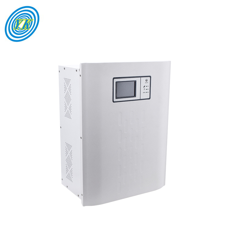
- ArchitectureHybrid Pure Sine Wave
- Nominal Input48 VDC Battery Bank
- AC Output110VAC / 220VAC (40A)
- InterfaceInteractive LCD Monitor
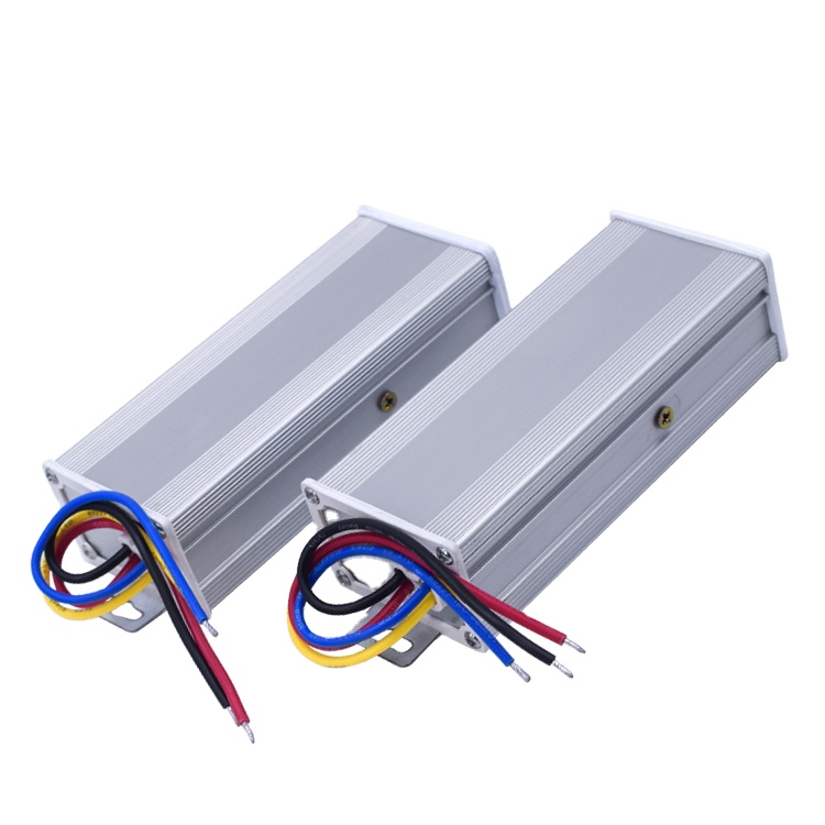
- Input Voltage40V–135V Wide Range DC
- Regulated Output12VDC @ 10A (120W)
- EnclosureAluminum Die-Cast IP68
- TopologyGalvanic Optocoupler Isolation
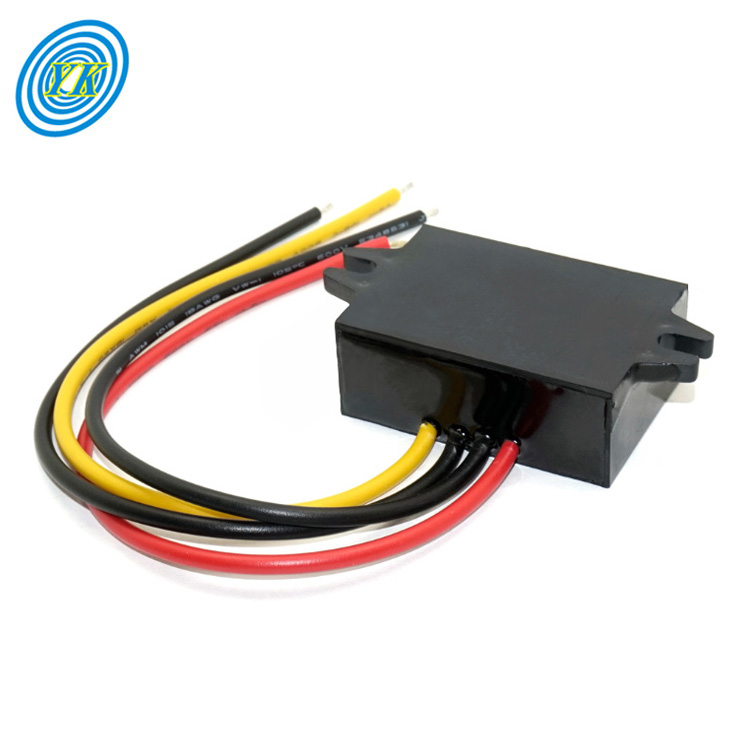
- Input Vector8V–35V Unregulated DC
- Regulated Output7.0VDC Precision 5A
- Peak EfficiencyUp to 96% Switching
- ProtectionOvercurrent & Thermal Cutoff

- Primary DC Bus12V Automotive Baseline
- USB Bus Output5V Regulated Dual-Tap
- Ripple & Noise<30mVp-p High Stability
- EncapsulationEpoxy Flame-Retardant Resin
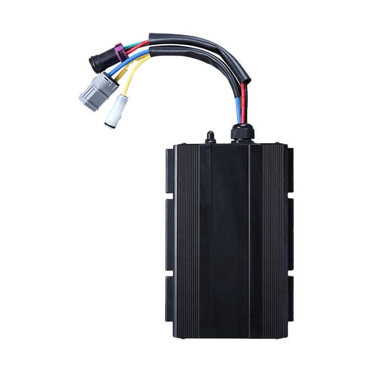
- Wide Input DC48V / 60V / 72V / 90V
- High Output Drive12VDC @ 42A (500W Continuous)
- Thermal DissipationFinned Aluminum Heatsink
- ComplianceCE, RoHS Class-B Industrial
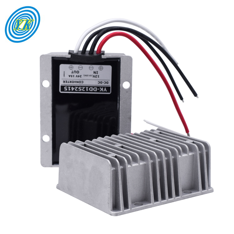
- Dynamic Dual Input12V / 24V System Switching
- Precision Voltage13.8V Float Charge Standard
- Current Threshold20A Continuous Heavy Duty
- Transient ClampIntegrated TVS Surge Diode
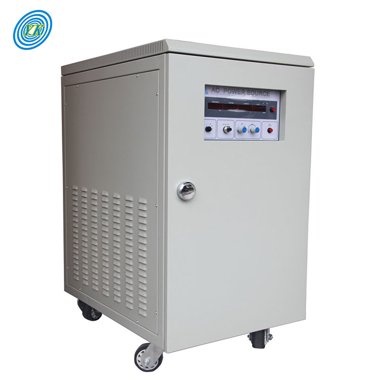
- Single Phase Grid110VAC / 220VAC (50/60Hz)
- Three Phase Plant220VAC / 380VAC Balanced
- Motor Starting SurgeRotary Inductive Dynamic Balance
- Duty Factor100% 24/7 Industrial Rating
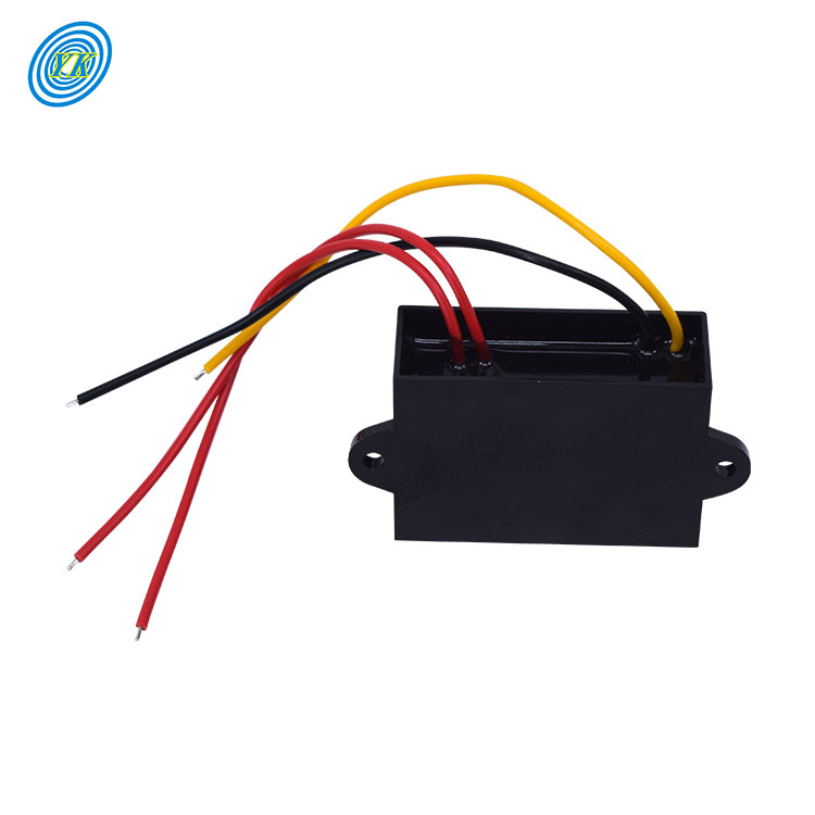
- AC Input Range10VAC to 26VAC Field Bus
- DC Output Bus5.0VDC @ 3A / 5A Peak
- Isolation RatingIndustrial Full Rectification
- Operating Temp-40°C to +85°C Ruggedized
Low Frequency vs. High Frequency Inverters: The Physical & Electrical Divide
Why mission-critical telecom grids, heavy marine pumps, inductive motors, and mining extraction nodes still mandate heavy iron-core LF architecture over lightweight high-frequency switching units.
1. The Magnetic Physics of Galvanic Isolation and Inductive Counter-EMF
The core distinction between a Low Frequency (LF) power inverter and a High Frequency (HF) inverter lies in the fundamental transformer topology and operating frequency of the electromagnetic conversion stage. High-frequency inverters eliminate heavy copper coils by utilizing solid-state PWM bridges operating between 20 kHz and 100 kHz, boosting low-voltage DC to high-voltage DC (typically 380V to 400V rail) via small ferrite transformers, and then modulating that rail into 110V or 230V AC through an H-bridge. While this reduces bill-of-materials cost, total weight, and physical dimensions by up to 70%, it sacrifices absolute electromagnetic resilience.
In contrast, Low Frequency Inverters invert low-voltage DC into a stepped AC waveform first, which is then fed directly into a robust line-frequency iron-core or toroidal transformer operating at 50 Hz or 60 Hz. This transformer acts as an impenetrable galvanic firewall between the DC battery bank and the AC load circuit. When inductive equipment—such as air conditioning compressors, hydraulic lift motors, commercial refrigeration pumps, or arc welders—disengages or cycles on, massive inductive kickback (counter-electromotive force, or counter-EMF) is reflected back into the circuit. High-frequency MOSFET switches without massive inductive dampeners easily suffer dielectric breakdown and avalanche puncture. The massive silicon steel lamination core and copper windings of a low-frequency inverter physically absorb, store, and dissipate these multi-thousand-volt spikes without component fatigue.
2. Toroidal Transformers vs. Laminated EI Transformers: Efficiency and Hysteresis
Within the spectrum of low-frequency manufacturing, the choice of magnetic core geometry dictates long-term thermal efficiency, acoustic resonance, and idle quiescent current draw. The traditional laminated EI transformer (composed of stamped E- and I-shaped electrical steel sheets stacked together) represents the legacy standard. Although cost-effective and mechanically straightforward to manufacture, EI transformers possess intrinsic magnetic air gaps at the mechanical joints of the laminations. These air gaps generate significant magnetic flux leakage, parasitic eddy current losses, and high no-load idle consumption, often drawing between 35W and 90W simply remaining energized on the battery bank.
Modern Tier-1 LF inverter manufacturers, including Varnix Technology, have migrated to grain-oriented silicon steel (CRGO) seamless toroidal transformers. Because the magnetic tape is wound continuously in a donut shape, magnetic flux runs parallel to the rolling direction of the steel grain without air gaps. This produces multiple measurable physical advantages: magnetic flux density increases up to 1.6 Tesla, acoustic coil hum is suppressed below 35 dB, total stray radiation is reduced by over 85% (critical for sensitive telecom receiver huts), and idle power consumption drops by more than 50% compared to equivalent EI cores.
3. Total Cost of Ownership (TCO) & MTBF Reliability in Extreme Climates
Procurement directors assessing remote infrastructure power systems must calculate Total Cost of Ownership across a 10-to-15-year horizon rather than initial unit acquisition costs. High-frequency inverters installed in humid, dusty, or unconditioned ambient environments (such as desert solar microgrids, off-shore oil platforms, or equatorial telecom towers) experience accelerated component degradation. The high-voltage capacitors and densely packed surface-mount transistors are vulnerable to moisture condensation, particulate tracking, and thermal runaway caused by rapid internal heating cycles.
Low-frequency power inverters feature massive thermal inertia. The heavy thermal mass of the iron core acts as a natural heat sink, smoothing out thermal spikes during rapid load steps. Operating with lower component counts and relying on heavy-gauge busbars and discrete TO-247 or screw-mount power semiconductors, low-frequency units deliver a Mean Time Between Failures (MTBF) exceeding 100,000 operational hours. In remote mining or off-grid communications facilities, the cost of sending an engineering crew via helicopter or all-terrain vehicle to swap a blown HF inverter exceeds the initial price differential of an industrial LF inverter within a single failure event.
Technical Comparison: Low Frequency vs. High Frequency Inverters
| Evaluation Parameter | Industrial Low Frequency (LF) | Commercial High Frequency (HF) | Engineering Impact & Selection Rationale |
|---|---|---|---|
| Surge Capacity (Inrush) | 300% rated capacity for 15–20s | 150%–200% for 10–50ms | Critical for inductive motor starts, refrigeration, sub-pumps |
| Galvanic Isolation | True physical magnetic isolation | Capacitive / non-isolated common ground | Protects sensitive battery banks and sensors from AC fault surges |
| Counter-EMF Absorption | High: Absorbed safely by copper mass | Low: Triggers immediate OVP fault shutdown | Prevents field failure when switching inductive heavy machinery |
| Total Harmonic Distortion (THD) | < 3% Clean sinusoidal profile | 3% to 6% Variable with load step | Essential for medical lab instruments, audio transmitters, servers |
| Hardware Weight & Form Factor | Heavy (18kg to 65kg+ per unit) | Lightweight (3kg to 12kg) | HF for RV rooftop/hand carry; LF for fixed plant/marine/infrastructure |
| MTBF Expectancy | > 100,000 Hours (10–15 Years) | 30,000–45,000 Hours (3–5 Years) | Dramatically lower replacement and service maintenance overhead |
| Acoustic & EMI Signature | Low EMI, mild 50/60Hz low hum | High HF switching noise & RF harmonics | LF complies with strict telecom and RF communication shelters |
Top 10 Low Frequency Inverter Manufacturers & Global Suppliers
A benchmark evaluation of the world’s foremost low-frequency power inverter engineering facilities, verified for quality control standards, manufacturing scale, and technological specialization.
Varnix Technology Co., Ltd.
Victron Energy
Schneider Electric (Xantrex)
OutBack Power (EnerSys)
Sensata Technologies (Magnum Energy)
Studer Innotec
SMA Solar Technology
Cotek Electronics
Mean Well
Sigineer Power
Future Procurement Trends in Low Frequency Inverter Engineering
Strategic hardware advancements that engineering buyers must consider when specifying capital equipment for the next decade of power electronics evolution.
1. Silicon Carbide (SiC) Hybrid Topology
The traditional silicon IGBT primary switching stages are rapidly being superseded by Silicon Carbide (SiC) MOSFET arrays. This hybrid approach pairs high-speed, ultra-low switching-loss wide-bandgap semiconductors with heavy low-frequency toroidal output transformers, driving total inverter full-load conversion efficiency past 96.5% while slashing quiescent magnetic heating.
2. High-Voltage CAN-Bus BMS Integration
Legacy LF inverters relied on coarse lead-acid voltage thresholds for state-of-charge tracking. Next-generation procurement specs require direct digital closed-loop communication over CAN bus and RS485 with industrial LiFePO4 battery management systems (BMS), dynamically calibrating charging current vectors down to 100-millisecond telemetry intervals.
3. Grid-Forming Synthetic Inertia Logic
As microgrids decouple from traditional fossil-fuel steam turbine rotating inertia, modern low-frequency inverters are being programmed with "grid-forming" droop algorithms. The massive magnetic field of the iron core acts as an electro-mechanical shock absorber, providing true synthetic inertia to stabilize instantaneous microgrid frequency swings.
4. Extreme Environment Solid Encapsulation
Industrial B2B procurement in mining, desert exploration, and near-shore maritime sectors is shifting toward fully vacuum-pressure impregnated (VPI) copper windings combined with IP65-rated sealed compartmentalization, preventing electrolytic corrosion and micro-arc tracking over multi-year deployments.
5. Solid-State Static Transfer Switches (STS)
Mechanical transfer relays with 10ms to 20ms transition latency are being replaced with zero-cross solid-state thyristor switches. This reduces AC line-to-battery transfer duration under 4 milliseconds, preventing sensitive industrial PLCs, computing nodes, and CNC controllers from resetting during power interruption.
6. Localized Warehousing & Modular Spares
In response to international shipping disruptions and critical supply-chain bottlenecks, tier-1 buyers prioritize OEMs that maintain bonded domestic warehouses (such as Varnix’s North American distribution facility) to ensure sub-assembly swappability and immediate warranty dispatch.
Why Tier-1 System Integrators Partner with Varnix Technology
Two decades of continuous manufacturing excellence, proprietary transformer fabrication, and rigorous QA protocol compliance trusted across 45+ international markets.
23 Years of In-House Precision Production
Founded in 2003, Varnix maintains complete physical control over winding, PCB surface mounting, enclosure CNC punching, and component assembly across 10+ dedicated lines in our 1,229 m² verified facility.
100% Full-Load Burn-In Aging QC
Every single power unit undergoes continuous high-temperature aging on automated resistive/inductive load test racks, supplemented by oscilloscope waveform profiling and dielectric hipot verification before boxing.
North American Overseas Stock
To eliminate 30-day ocean transit lead times for time-critical utility installations, Varnix maintains high-velocity inventory of core DC-DC converters and inverters directly in our US domestic warehouse.
Complete OEM / ODM Customization
Our engineering division designs customized primary/secondary voltage windows, tailored LCD menus, proprietary firmware communications protocols, and private-label silk-screening from prototype to mass production.
Independent SGS Factory Audited
Our quality management system is fully certified to ISO 9001:2015, with all core commercial product lines holding verified CE, RoHS, and FCC certification backed by transparent third-party test reports.
Dedicated 24/7 Global Engineering Desk
Direct communication with certified power electronics engineers ensures rapid resolution of sizing questions, schematic reviews, and after-sales support with a verified 98.2% response rate.
Engineering FAQ: Low Frequency Inverter Sizing & Integration
Critical considerations addressed by our Senior Application Engineers to streamline your system specification process.
Why do inductive loads specifically require a low-frequency inverter over a high-frequency model?
How do I correctly calculate the required DC input cable gauge and fuse sizing for an industrial LF inverter?
Formula: Maximum DC Current (A) = Rated Continuous AC Watts / (Low Voltage Cutoff × Inverter Efficiency)
For example, a 3,000W continuous inverter running on a 48V nominal battery bank with a 42V low-voltage disconnect and 90% efficiency will draw:
3000 / (42 × 0.90) = 79.4 Amps. In contrast, running that same 3,000W system from a 12V battery bank (10.5V cutoff) results in: 3000 / (10.5 × 0.90) = 317.5 Amps! This dramatic amperage increase mandates massive 4/0 AWG pure copper welding cables and 400A Class-T fuses to prevent dangerous resistive I²R heat dissipation and voltage drops.